

Banner image credit @sahandbabali on Unsplash.
Blues University is an ongoing series of articles geared towards beginner- and intermediate-level developers who are looking to expand their knowledge of embedded development and the IoT.
Introduction
Since its founding in the early 2000s, Arduino has been synonymous with electronics experimentation and making. While Arduino as a company designs, develops, and manufactures its own development boards – circuit boards that include a microcontroller chip and the supporting electronics needed to run it – they also make the Arduino IDE (integrated development environment) software package, as well as the Arduino Cloud for programming. This has been extended to work with a wide range of third-party boards and even bare chips.
This Arduino beginner's guide will outline how to get started programming in the Arduino IDE, using the official Arduino Uno (R3), and move on to using more advanced boards in Chapter 5. Arduino programs are written in a derivative of C, and individually known as sketches, evocative of creating something new that can be perfected over time – or left as an experiment. Since drivers and device firmware are typically taken care of behind the scenes, users can get started creating in short order!
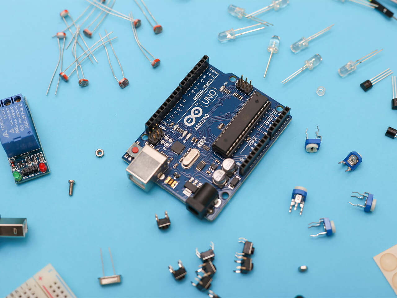
Chapter 1: What is Arduino?

Image Credit: Jeremy Cook
Briefly, Arduino is a prototyping platform for physical computing experimentation. This can mean the Arduino IDE, and/or the physical board itself. Official Arduino boards are manufactured by Arduino.cc, including the Arduino Uno, Arduino Nano, and many others. Clones of Arduino's official open-source boards are also available, which are software compatible and have nominally the same electrical characteristics, but are not permitted to use Arduino branding.
Derivative boards are devices that take an open source Arduino design and build upon it to make something with different characteristics. For example, one could redesign an Arduino Uno with an array of transistors for driving heavier loads than with its standard I/O, or make a pared-down device meant for wearable use. Boards that have no clear Arduino ancestor, but can be programmed with the Arduino IDE, could also be considered derivatives. This category would include advanced boards like the STM32-based Blues Swan (discussed in Chapter 5), or even an ATtiny85 breadboard with minimal components.
Arduino boards can be extended with additional hardware. In the case of the Arduino Uno – or the many derivative and clone boards made in the Uno form factor – this often means using expansion boards known as shields, which plug into the device's female headers. In other instances, the I2C or SPI protocol can be used to interface with external hardware. When neither fits a particular situation, General Purpose Input/Output (GPIO) pins provide another alternative.
The Arduino IDE can also be expanded, using add-on software packages known as libraries (discussed in Chapter 5). Once installed, developers can call functions from included libraries within a sketch, abstracting functionality that would otherwise make programs more complex.
All of this allows an Arduino to blink an LED, read digital and analog inputs, output analog signals via Pulse Width Modulation (PWM), and much more. An Arduino can form the heart of your robot, car, or IoT device, or you can use it to simply blink an LED. There is a vast amount of hardware and example code readily available, and the limit to what you can do with it is only your imagination.
Why the Name "Arduino"?
The Arduino ecosystem was birthed out of the Interaction Design Institute Ivera in Italy, home of King Arduin, ruler of Italy from 1002 to 1014 AD. The modern-day Bar di Re Arduino honors (or did honor as of circa 2010) his memory, and was a favorite gathering spot for Arduino co-founder Massimo Banzi. Arduino was thus named after this bar and/or the historical Italian king.
Is a Raspberry Pi an Arduino?

Is there something here that doesn't belong? Image Credit: Jeremy Cook
A traditional Raspberry Pi (e.g. RPi 4/5, RPi Zero, etc) is an SBC or single-board computer. While they can perform Arduino-like functions with their GPIO pins, they would more accurately be called computers, not microcontroller development boards like the Uno et al. They are not programmed with the Arduino IDE.
The RPi Pico and Pico W, however, are microcontroller development boards, and can be programmed in the Arduino IDE with the proper software setup. So one could define the Pico as a derivative Arduino board.
On the other hand, one could also call Sonic the Hedgehog a Nintendo game since it's available on the Nintendo Switch. Both are correct in some sense, though neither really feels correct.
Chapter 2: Blinking an LED with the Arduino IDE

Image Credit: Jeremy Cook
In traditional computer programming, printing Hello World! is considered the
first step towards further programming. The equivalent for microcontrollers is
blinking an LED. To accomplish this task, first
download the Arduino IDE for your
particular OS. Screenshots and further instructions will be generated on macOS,
but the Arduino IDE is also available on Windows and Linux with minor
differences. You'll also be using the classic Arduino Uno for initial
demonstrations; however, these instructions are broadly applicable to many other
boards.
Once installed – macOS is fairly standard: open the .dmg file, drag into
applications – open the Arduino IDE and acknowledge that it is a scary program
from the Internet if requested. You'll then be greeted with a text input field
including a void setup() and void loop() section, each bounded by a set of
brackets {}. Setup runs once to set up your program, while the loop
section runs continuously. In some circumstances, such as setting up global
variables (storage locations for mutable values), you will place code outside
either section.
Connect your board to the computer – the classic Arduino Uno uses an old-style USB-B connector – and click on Select Board in the Arduino IDE window. Select the connected Arduino Uno in the drop-down menu. If you're not quite sure if you have the correct device, you can always disconnect then connect the board to see if it disappears and reappears.

Image Credit: Jeremy Cook
At this point, you can send the blank program to your board by simply hitting the upload arrow near the upper-left-hand corner of the Arduino IDE. This can provide some confirmation that things are operating correctly, but once programmed, your board is still a rather ineffective paperweight. To make it do something, navigate to File > Examples > Basics > Blink to load a blink sketch. Hit the upload icon, and the onboard LED will blink on or off once every second.

Image Credit: Jeremy Cook
Congratulations, you've officially programmed your Arduino! You'll examine
this code more in Chapter 3, but for now, examine the digitalWrite() and
delay() functions. Change one or both the delay numbers around
(expressed in milliseconds). Hit the upload button again to see what happens!
Chapter 3: Delving Into Sketches: Basic Arduino C Coding
In this (somewhat longer) chapter, you'll examine two very basic Arduino example sketches, then show how an input can be used to conditionally blink an LED. In addition to your Arduino, grab a length of jumper wire, and a standard LED.
Example 1: More Blinky Blinky

Image Credit: Jeremy Cook
Let's take another look at the blink sketch loaded previously:
In the void setup() section, you have the statement:
pinMode(LED_BUILTIN, OUTPUT);This code sets the pin designated as LED_BUILTIN as an output pin. Here,
LED_BUILTIN is a special built-in alias for pin 13, and you can substitute
"13" for LED_BUILTIN here and in the section below if you so desire.

The void loop() section runs over and over, starting with setting the LED pin
HIGH via:
digitalWrite(LED_BUILTIN, HIGH);digitalWrite functions start with the pin number after the parenthesis, a
comma, then the state of HIGH or LOW. There's then a delay(1000) function,
which stops the program for 1000ms, or 1 second. The LED is then set to LOW
via the second digitalWrite command, and another delay is performed before
turning the LED HIGH again.
To control an external light, plug in a positive LED leg (typically the longer
one) up to GPIO pin 12 and negative to ground. Change all instances of
LED_BUILTIN to 12, upload, and it will blink the external LED in the same
manner as the builtin device. Test other pins as desired. Ideally, you would
also use a resistor in series to avoid excessive current, but going without is
generally not an issue for testing.

Insert your LED. Adding an inline current limiting resistor would be ideal.
Example 2: Analog Input, Serial Output
Open up the File > Examples > Basics > AnalogReadSerial sketch to explore analog input and serial communication concepts.
In line 16, the Serial.begin(9600); function initializes serial communications
at 9600 baud. This allows the Arduino board to send signals to the Arduino IDE's
serial monitor for feedback. Higher or lower data rates may be set, but the
serial monitor must be set to the same speed to communicate properly.

In line 22, int sensorValue creates the variable sensorValue, which is
explicitly declared as an int, or integer. In this context, integers are whole
number values between -32,768 and + 32,767 (-2^15 and +2^15 -1).
= analogRead(A0) then sets sensorValue to a representation of the voltage
sensed on A0 between 0 and 5V, scaled to between 0 and 1023 (a 10-bit value,
stored in the 16-bit sensorValue variable).
Line 24 then outputs this value via Serial.println(sensorValue); to a
connected computer or other device. Line 25 adds a 1ms delay, which makes the
data more readable, and keeps the serial line from getting swamped. Line 25 is
somewhat optional, so if you would like to experiment and take this out, insert
two forward slashes // to turn the line into a comment. Commenting code to see
the results can be a useful troubleshooting technique.

Upload the unmodified code, then hit the serial monitor icon in the
upper-right-hand corner of the Arduino IDE. You'll be greeted with a value on
the low side of 0 to 1023, representing an unconnected, or floating pin, and
thus an undefined voltage. Plug the jumper into A0, and the number will
continue to bounce around, even more so if you grab the unconnected lead. To
further visualize this pin's behavior, open up the serial monitor next to the
plotter icon. This sort of floating input is typically undesirable.
To read known voltages, plug the unconnected jumper lead into a ground pin, and
the A0 reading will be pulled to a consistent zero. Switch to the Arduino's 5V
header, and you'll be greeted with 1023 (5V/5V * 1023). Switch to 3.3V, and r
eadings will come out to 3.3V/5V * 1023, or around 675.
To get the actual voltage seen on your Arduino pins, open and load the
Examples > Basics > ReadAnalogVoltage sketch, which includes line 24:
float voltage = sensorValue * (5.0 / 1023.0);. Here voltage is defined as a
float, a number with a decimal point, and the calculation will give you a result
in actual voltage levels on the serial monitor.
Congratulations, you've made an Arduino voltmeter!

Image Credit: Jeremy Cook
Example 3: Making Digital Decisions

Image Credit: Jeremy Cook
Blinking an LED and reading voltages are interesting first steps, but the power of an Arduino is to take in inputs and produce corresponding outputs. Here you'll learn how to programmatically control an LED using a jumper wire as a switch. You'll also be introduced to the concept of digital inputs.
Open File > Examples > Digital > Button, and upload to your board. Connect a
jumper to pin 2 to act as your switch. Connect the other end to 5V to set pin
state 2 HIGH, and the Arduino will turn the LED on in response. Switch the
jumper to GND to set the pin LOW, thus turning off the LED.

Before the setup and loop sections, two global constants (values that don't
change), buttonPin and ledPin, and a variable, buttonState are declared,
allowing them to be used anywhere in the program. Declaring values upfront
allows changes to be made in one place, rather than modifying values throughout
the program.
In the setup section, ledPin is declared as an output, while the buttonPin
is declared as a digital input, via lines 34 and 36. Note that this is setting
the pins that constants ledPin and buttonPin represent to their respective
states. They could also be input explicitly as 13 and 2, though this quickly
becomes cumbersome as programs expand.
In the loop section, the buttonPin status (i.e. the jumper) is checked on
line 41:
buttonState = digitalRead(buttonPin);With that information, a decision is then made on whether to energize the LED
via lines 44 to 50. Note that lines starting with // are comments and don't
affect the sketch's operation. Comments are left out below:
if (buttonState == HIGH) {
  digitalWrite(ledPin, HIGH);
}
else {
  digitalWrite(ledPin, LOW);
}
Expanding on this, if the button state (i.e. jumper wire) is in a HIGH state
(5V), the ledPin will be illuminated. Otherwise, the pin will be turned off –
pulled LOW per the else statement. One could substitute in if
(buttonState == LOW) for the else function, which may be necessary if there
are more than two options. Note that == is a comparison operator, checking
whether something is true. = instead assigns a value to a variable, as seen in
this sketch and elsewhere.
The button state is either HIGH or LOW – 1 or 0 – the digital language of
computers. Computers can make decisions based on these input 1s or 0s, and
output 1s and 0s, in the form of (among other things) turning an LED on or off.
Decisions can also be made via analog input, but even this is, ultimately, a
digital approximation of a real-world value. For example, the 0 to 5V inputs
seen earlier were ultimately distilled down to combinations of 0s and 1s that
represent values of between 0 and 1023.
While 5V (HIGH), and ground (LOW) are well-defined, when the jumper is not
connected, you again see a floating or undefined value, resulting in an LED that
may be on or off. Ways to avoid this situation are discussed in
Chapter 6: Common Issues and Troubleshooting.
In summary, use a high-value resistor to pull it one way or another when
otherwise disconnected.
Chapter 4: Add Capacitive Sensing and More With Arduino Libraries

Image Credit: Jeremy Cook
There are a wide range of functions built into the Arduino IDE. At the same time, you could argue that there are an infinite number of functions that aren't in the Arduino IDE. The good news is that additional code functionality can easily be added in the form of custom libraries. Here you'll explore adding capacitive sensing capabilities to an Arduino Uno.
To install the needed library for capacitive sensing, click on the Library Manager (books) icon on the left of the Arduino IDE and search for "adctouch." The first option that comes up should be "ADCTouch by martin2250". Click install and let it get to work. Navigate to File > Examples > ADCTouch > Buttons to load the included example sketch for this library.

Examining the code, the first line:
#include <ADCTouch.h>...commands the Arduino IDE to include this library when compiling a program, allowing you to access functions as if they were explicitly written into your sketch. In this way, libraries abstract functionality, making programs much easier to write (and read).
Plug in your Arduino and upload code, then open the serial monitor to see
readings. Insert a jumper into A0 and/or A1, then touch the conductor(s) to
see the reaction. The program is able to detect capacitance added to the system
by the human body, which can make an excellent substitute for a physical button
in many situations.
To make A0 into a digital input, plunk in the following line in the setup
section:
pinMode(LED_BUILTIN, OUTPUT);Additionally, add the following in the loop section before the Serial.print
statements:
if (value0 > 100) {
  digitalWrite(LED_BUILTIN, HIGH);
}
else {
  digitalWrite(LED_BUILTIN, LOW);
}
Modified Buttons example
This code should look familiar from previous coding examples, but instead of an
== comparison operator, the > comparison operator after value0 tells it to
do something if it's greater than a set value (100 in this case). This is
similar to the methodology that could be used to make decisions based on analog
voltage values. Note that capacitive sensing can be implemented using pads on a
printed circuit board, opening up possibilities for mass production.
Capacitive sensing is outlined as a useful and accessible library example.
However, there are many, many libraries that let you work with everything from
stepper motors, to addressable LEDs, and more. Note that not every library is
available via this search interface. When needed, you can also add libraries via
a .zip file downloaded via GitHub or elsewhere. Navigate to Sketch > Include
Library > Add .ZIP Library and select the .zip library.
Branching off On Your Own
With these basic programming concepts, and the ability to add on to the Arduino IDE, you're ready to create your own program from scratch. The possibilities are endless, but if you need some pointers or ideas, navigate to File > Examples to find a wide variety of code for different situations. As seen here, add-on libraries also often provide usage examples, found under File > Examples, under the Examples from Custom Libraries heading.
One idea for where to start in your example code journey is found in File > Examples > Control > ForLoopIteration. This sketch shows how to create programmatic loops, which are extremely important for writing good code.

Chapter 5: Adding New Boards to the Arduino IDE
While there are a number of boards built into the Arduino IDE, the ability to add new devices opens up a wide range of possibilities. The great news is that with the Arduino IDE 2, installation of many such boards is quite easy. Others take an additional step (still fairly simple), which you'll learn about in the context of the Blues Swan board.
The Easy Way

Image Credit: Jeremy Cook
If you have a board that's not built-in to the default Arduino IDE installation, simply plug it in via USB, and when the board is selected it may ask you if you want to install the needed core. Click yes, and it will take care of things for you. You can also search for the board in question via the boards manager icon in the left of the Arduino IDE (above the library manager) and install it there. For the Arduino Nano 33 IoT board, shown in the image above, you can then upload and run the same blink sketch outlined in Chapter 2. This board, and many others, also come with a built-in LED for diagnostics and indication purposes.

The Extra Step Way
In some cases, such as the Blues Swan MCU, you'll need to go through the step of adding an "Additional boards manager URL". Search for "blues" if you like, and note that it doesn't (yet) come up.
To solve this issue, navigate to Arduino IDE > Settings and click on the Additional board manager URLs: text entry box. Here, paste in a board manager URL provided by the device's manufacturer, and hit OK. In this case, the address is:
https://github.com/stm32duino/BoardManagerFiles/raw/main/package_stmicroelectronics_index.json
Click on the Boards Manager again, and search for "blues." Install what comes up, noting that several other boards besides the Swan are in included in this package. This procedure adds the proper board definition in the Arduino IDE, allowing it to work with the new device. Things may vary somewhat from here depending on the board. Further steps as specific to programming the Swan via USB.
Open the "blink" sketch as outlined earlier and plug in the Swan board. It does not come up in the standard board selection dropdown. Instead, navigate to: Tools > Board > STM32 MCU based boards and select Blues boards. The board will now appear as if it was selected in the dropdown. Navigate to: Tools > Upload method > STM32CubeProgrammer (DFU)


Hold the boot select button on the Swan (black button further from the USB
port), momentarily depress the reset button (white button), then release the
boot button. Hit upload, and your board will start blinking away. Note that
you'll need to perform the reset/boot button procedure each time you program the
Swan. More information on using the Arduino IDE with Swan
can be found here.

Chapter 6: Common Issues and Troubleshooting
While the Arduino ecosystem is relatively straightforward, there are a few gotchas that new – and even experienced – programmers and hardware hackers often overlook. Here's a very brief list of some things that you might run into starting out...and that you might be embarrassed to overlook later!

Image Credit: Jeremy Cook
The Arduino IDE is case-sensitive: digitalWrite is not DigitalWrite,
digitalwrite, or DIGITALWRITE. Also, it's not digital write. One great way
to keep from copious capitalization and/or spelling errors is to use the Arduino
IDE's autocomplete feature, which will pop up suggestions as you type. If this
is not enabled, go to Arduino IDE > Settings and mark the checkbox for
Editor Quick Suggestions.
Comparison vs Assignment Operator: As seen in Chapter 3, Example 3, the
Arduino IDE uses the == comparison operator to test if one value is equal to
another. In contrast, the assignment operator = assigns a value to a variable
(e.g. int x = 1;). = and == can easily be confused, causing an error in
your code.
Floating Pins: If you hook an analog pin up to nothing, the reading isn't
definitively true or false, but is random, or at least unreliable. To keep
pins in a known LOW state when not actively switched, use a high-value
resistor (e.g. 10k) and connect it to ground at all times, pulling the input
LOW by default. A positive input from a button or other device will overpower
this small resistor to make the input read HIGH.
Alternatively, you can set pins as INPUT_PULLUP, which causes the
microcontroller to pull pins HIGH when there is no other influence on them.
Here, a LOW input indicates an active state. An example of how to do this is
found in File > Examples > Digital > DigitalInputPullup. While convenient,
the somewhat non-intuitive LOW-active behavior must be considered in your
hardware and software design.
Bouncing Switches: When flipped on, switches literally bounce between being connected and disconnected until settling into a stable state. To us as humans, this happens instantaneously. On the time scale of computers and microcontrollers, such bouncing can be an appreciable problem that causes errant code execution. The basic solution to this problem is to program in a delay so that a switch is not acknowledged until it's in a consistent steady state, and an example of how to do this is found in File > Examples > Digital > Debounce. Dedicated libraries and hardware solutions are also available that may be appropriate for your project.
Power Limitations: While Arduino pins are perfect for digital signaling, and capable of directly powering an LED or two without issue, typically they aren't suitable for anything demanding power-wise by themselves. To control more power with an Arduino board, you can use transistors and relays (and a wide range of variations on that theme) to handle larger currents.
Computer Interface Issues: Version 2 of the Arduino IDE has some fantastic enhancements over its predecessor, including the drop-down menu that largely takes care of port and board type assignment based on what is connected. At the same time, if you need more granular control of your connections (e.g. using the Blues Swan in Chapter 5) navigate to Tools > Board to select your board type directly and Tools > Port to select the port where your device is connected. Depending on your particular board, the tools menu has a number of other settings that can also be adjusted.
Chapter 7: Go Make Something!
What's presented here is but a brief introduction to the world of Arduino and physical computing. While novice programmers will appreciate the Arduino IDE's straightforward setup – and its expansive ecosystem of tutorials and example projects – you can also perform Arduino-style programming via PlatformIO in Microsoft Visual Studio Code. This is a fantastic tool for advanced (and advancing) programmers, which can take your Arduino experimentation to the next level.
If you've read this far, you probably have a wide variety of ideas for how you might use the Arduino ecosystem for any number of projects. If you do need extra inspiration, here are a few of our favorite projects:
ClearCrawler Remote-Controlled Strandbeest
An Arduino Nano forms the brains of this device, which walks on eight Theo Jansen Strandbeest-style legs. The Arduino moves its two powerful leg motors indirectly via a motor driver board, and controls two LED matrix eyes. To its credit (and/or detriment), this robot was constructed by Jeremy Cook, the author of this guide.
44-Furby Organ Uses a Multitude of Arduino Nanos
Furbies were a line of toys from the 1990s which chattered about in their own language, acting somewhat lifelike. While many of us have forgotten (or tried to forget) these devices, Sam Battle of Look Mum No Computer has instead cranked the Furby concept up to the proverbial 11. His Furby organ/choir uses 44 of these things/beings for music-making, with the help of many, many Arduino Nano clones for control. It's mind-blowingly weird and amazing.
Smart Water Quality Monitor

While the Arduino ecosystem is great for fun and games, it's not all fun and games. In this project, Zak Fields shows how he created an off-grid device for gathering pollution data for a local stream. This device uses a Blues Notecard to push data to the cloud via cellular, along with a Notecarrier A to facilitate connections and power management. An Adafruit HUZZAH32 ESP32 development board (Arduino ecosystem) is used for processing.
Blues: Wireless Connectivity for the Arduino Ecosystem and More
We hope that this guide gave you the tools to get started on your Arduino and physical computing journey, and the inspiration to make something of your own. The options for what you create, and where you go from here, are virtually limitless. If you'd like to add wireless IoT connectivity to your project – sans monthly billing – Blues offers a number of excellent solutions to get your data to the cloud and back from nearly anywhere!
This article if part of a broader series where you can dig deeper into each aspect of embedded development. To embark on this journey, be sure to follow Blues University, where you can explore and contribute to shaping the future of IoT.
If you're new to embedded development and the IoT, the best place to get started is with the Blues Starter Kit for Cell + WiFi and then join our community on Discourse. 💙
Jeremy Cook is an engineer and tech journalist who has spent over a decade in process automation. You can find him on Twitter, YouTube, and elsewhere on the Internet, where he’s best known for his electronics experimentation and robotics builds.

Image Credit: Jeremy Cook