

Blues University is an ongoing series of articles geared towards beginner- and intermediate-level developers who are looking to expand their knowledge of embedded development and the IoT.
Breadboard use is a fundamental skill for anyone exploring embedded development. It lets you prototype and test circuits temporarily with reusable parts before committing to a final design.
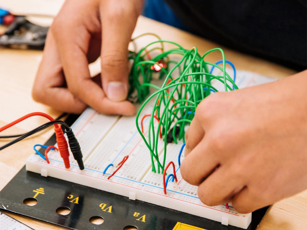
This hands-on guide brings theoretical concepts to life, fostering a deeper understanding of how components interact within a circuit. We take a step-by-step approach to wiring a breadboard, using a kit that includes a breadboard, a power source, wires, and resistors, alongside the Swan, an STM32-based microcontroller from Blues.
To follow along, find a similar breadboard kit online (there are many examples of "Arduino Starter Kits" or "ESP32 Starter Kits" on Amazon for instance). Even better, head to your local electronic component shop and they can provide the best guidance.
You don't need any previous electrical experience to be successful with this guide!
What Is a Breadboard?
A breadboard, particularly the type discussed in this article, is a physical platform that simplifies constructing electronic circuits. It lets you create a circuit similar to a printed circuit board (PCB) without permanent soldering. This approach is perfect for experimenting with circuit designs before making them permanent.
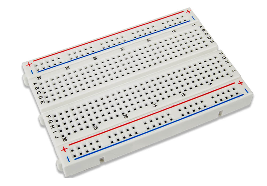
At first glance, a breadboard looks like a plastic board punctuated with a grid of holes. However, underneath the surface, these holes are connected in specific ways that facilitate connecting electronic components and wires.
The breadboard's internal workings consist of metal strips that run underneath rows of holes. When you insert a wire or a component's lead into a hole, the metal strip grips it, creating a stable electrical connection.
The holes in each row in the primary region connect horizontally. So, when you plug a component into a row, you can easily plug another component or wire into the same row to connect them. This feature enables connecting multiple branches at the same node, so it's an ideal tool for complex circuit designs requiring numerous connections at a single point.
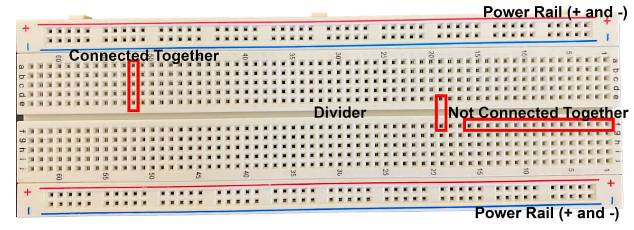
The power rails, running along the breadboard's sides, function differently. They connect vertically, providing a common point for power and ground connections along the breadboard's length.
This organization of connections in the central area and on the power rails provides a systematic and intuitive way to build your circuit. It's like having an electrical playground where you can view and modify how various components interact by simply plugging them in or pulling them out.
When you're first starting to work with electronics, understanding and using a breadboard is a foundational skill. It demystifies circuit design, providing a practical way to explore, learn, and innovate.
Here are the main components of a breadboard:
- Tie points: These tiny holes are where you insert component leads or wires.
- Power rails: These rails supply power to your circuit. You can usually find them on the breadboard's sides.
- Isolated rows and columns: These grids are where you place most of your components. They help connect various parts of your circuit.
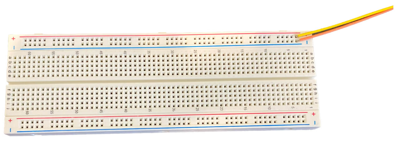
The image below shows a typical breadboard, with the power rails marked and notes indicating which types of holes are connected:
How to Use a Breadboard
Understanding a breadboard's layout is crucial, as it dictates how the board makes connections.
The central area is usually reserved for integrated circuits or any other component spanning the middle gap. The other rows and columns are for other components and wires. The power rails on the sides are ideal for providing power and ground connections to your circuit components.
You use small sections of wire to connect nodes (a row of holes), providing a completed path where the electricity flows. A circuit should always go from the positive rail to the negative rail (as long as you supply power to the positive rail and ground the negative rail) through whatever components you desire.
Later, you'll learn how to wire a completed circuit.
Essential Tools and Components
To get started on breadboard projects, you'll need a few essential components:
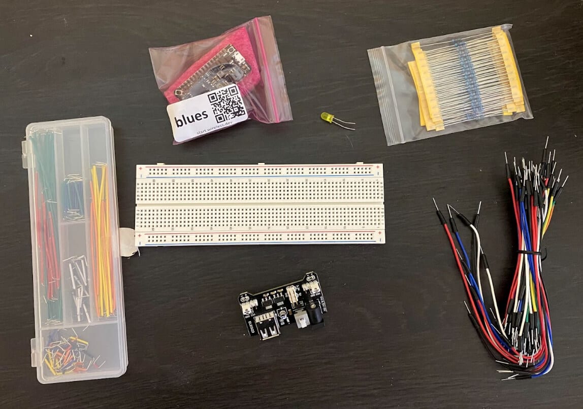
Development board: Embedded programs run using hardware like these development boards (a.k.a. host microcontrollers or MCUs). They're versatile tools for building and testing electronic circuits. Integrating a development board with a breadboard expands its functionality. This article uses the Swan microcontroller from Blues.
Power source: A reliable power source is crucial. You can use batteries, a USB connection, or a bench power supply. Keep in mind that you're working with DC electronics here, so choose your power source accordingly.
Jumper wires: Jumper wires are available in three variants: male-to-male, female-to-female, and male-to-female. Each type serves a specific purpose in making breadboard connections. Male ends feature a protruding pin to plug into various components, while female ends are designed to have objects plugged into them. Male-to-male jumper wires are the most frequently used, especially when connecting two ports on a breadboard. For this demonstration, you'll be using male-to-male jumper wires.
Basic components: It's essential to have a selection of LEDs, resistors, capacitors, and switches to experiment with various circuit configurations. This guide uses a single resistor and a single LED.
Multimeter: While a multimeter is optional, it's useful for measuring and verifying voltages and currents and ensuring correct connections.
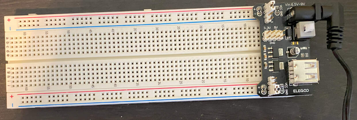
The image below depicts a breadboard with all its components:
Step-by-Step Guide to Wiring Your First Circuit
Step 1: Setting Up Your Workspace
Ensure you have a clean, well-lit area with all the necessary components within reach.
Step 2: Connecting the Power Source
A. Identify the Power Rails
You'll find two long columns of holes on either side of your breadboard, usually labeled with a red line and a blue or black line. These are your power rails.
The red line indicates where the positive voltage will go, and the blue or black line is for the ground (GND) connection.
B. Choose a Power Source
Choose a power source: batteries, a USB power supply, or a bench power supply. Ensure the source's voltage matches your circuit's requirements. Typically, the power source should be between 5 and 8 volts.
C. Connect the Power Source to the Breadboard
Now, take two jumper wires. Connect one end of the first wire to your power source's positive terminal and the other end to any hole along the breadboard column marked with the red line, the positive power rail.
Similarly, connect one end of the second wire to the power source's negative terminal and the other end to any hole along the breadboard column marked with the blue or black line, the ground power rail. The image below shows where to connect the wires to the breadboard:
Repeat this process if you want to power the positive and negative rails on the breadboard's other side.
Sometimes, you use a device to connect the power supply to the rails, like in the image below. It's the same concept in a more user-friendly package.
D. Verify the Connections
Before proceeding, it's wise to double-check your connections. Ensure that the positive wire from your power source connects to the breadboard's positive power rail and the negative wire connects to the ground power rail.
E. Test the Power Supply
If you have a multimeter, set it to measure DC voltage. Check the voltage across the power and ground rails to ensure it matches the power source's expected voltage.
This setup establishes a common power and ground connection accessible anywhere on the breadboard. It provides the necessary power to all parts of your circuit as you build it. This easy access to power is one of the many advantages of using a solderless breadboard to prototype electronic circuits.
Step 3: Create a Simple Circuit
Setting up a simple circuit on a breadboard marks the beginning of a practical understanding of how electronic components interact. The goal here is to light up an LED, a straightforward yet enlightening experiment. 💡
Start by identifying the LED's longer leg (the positive anode) and the shorter leg (the negative cathode). Next, select a resistor. A 330-ohm resistor is a good choice for a standard LED. Although you can determine a resistor's resistance by its color bands, you don't need to worry about that for this experiment.
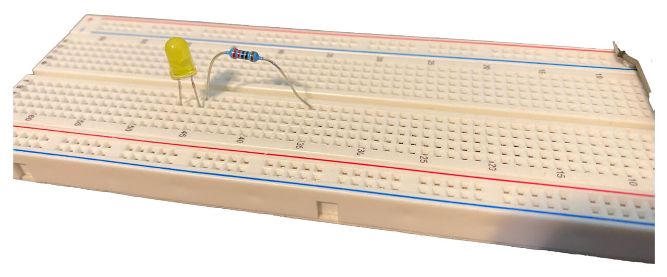
Now, place one leg of the resistor into any hole in a breadboard row. Connect the LED's anode to another hole in the same row, connecting the LED and resistor in series. Remember that the rows are the shorter distance across the board, and you can connect up to five pieces in one row.
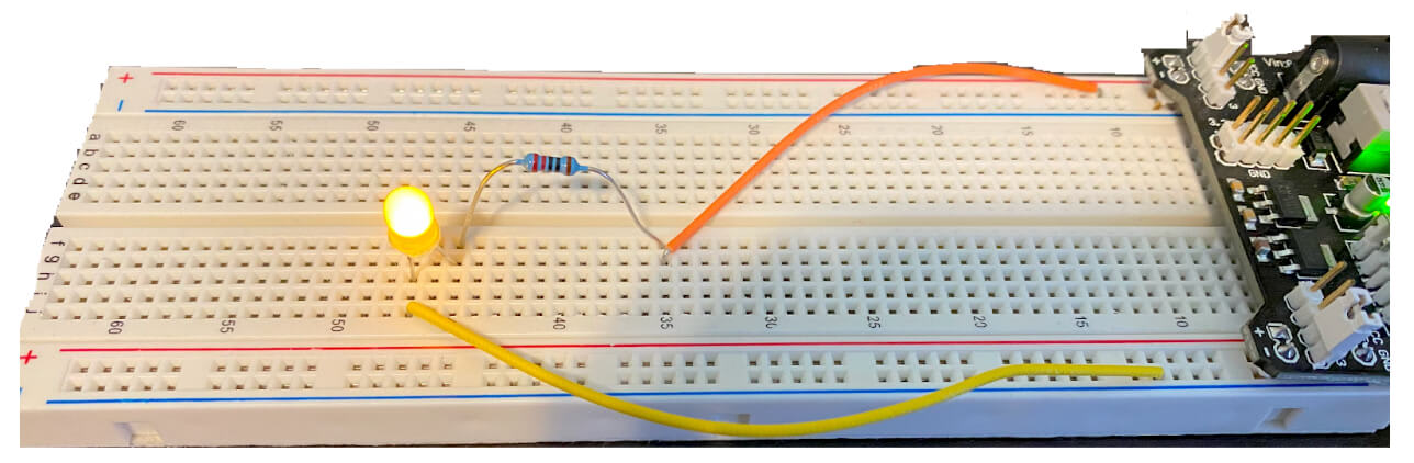
Plug the resistor's other end into any other row. Then, plug the LED's other leg into a separate row. When finished, it should look like the image below:
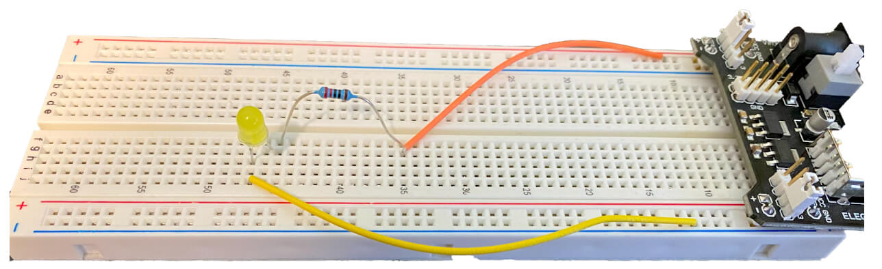
Now, to establish the power connections, connect one end of a wire to the breadboard's positive power rail (indicated by a red line). Connect the wire's other end to the resistor's other leg. This way, the positive voltage will travel through the resistor before reaching the LED, controlling the amount of current that flows through.
Next, connect one end of another wire to the LED's cathode and that wire's other end to the breadboard's negative power rail (indicated by a blue or black line). This action completes the circuit by providing a return path to the power source.
The image below shows the resulting circuit:
Once everything is securely connected, power on your power source. The LED should light up, indicating a successful setup. If the LED doesn't light up, double-check its orientation: It's polarized, so it only works when inserted correctly.
The resistor plays a crucial role in this simple circuit! It ensures the LED receives a safe amount of current, preventing it from burning out.
This basic setup provides a practical understanding of how a simple circuit operates while laying the foundation for exploring more complex circuit configurations on a breadboard. The breadboard's modular and reusable nature makes it an invaluable tool for delving deeper into the fascinating world of electronics.
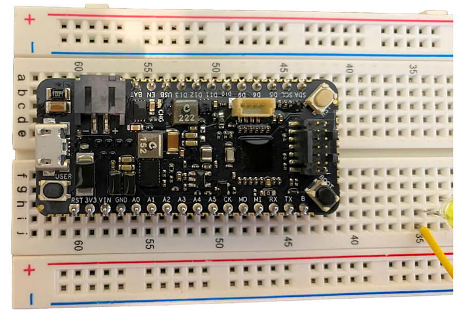
Step 4: Placing the Development Board
The development board looks like a big circuit with a series of pins sticking out. These pins are its inputs and outputs.
Since each pin is unique, it's crucial to ensure that they're not connected together. Position the development board on the breadboard so that the pins are on opposite sides of the middle divider. This placement ensures that the pins aren't wired together in any way.
In the image below, the development board safely straddles the central division:
Step 5: Wiring the Development Board
You can power the Swan development board similar to how you delivered power to
the LED and resistor circuit. The pins on the development board are marked for
easy identification. To power the development board, you'll connect the VIN
pin to the power source and the GND pin to the breadboard's negative rail.
 warning
Carefully observe the development board's safe voltage range. For example, this
tutorial's Swan board has a safe operating range of 2.5 to 5.5 volts. If your
power source delivers more than 5 volts, you must insert resistors between the
positive rail and the VIN pin to reduce the voltage to around 5 volts.
To lower the voltage, create a circuit similar to the LED circuit above and test the voltage after the resistors. If it remains too high, simply add more resistance. In this demo, using a 5V power supply means you won't deliver too much voltage to the board.
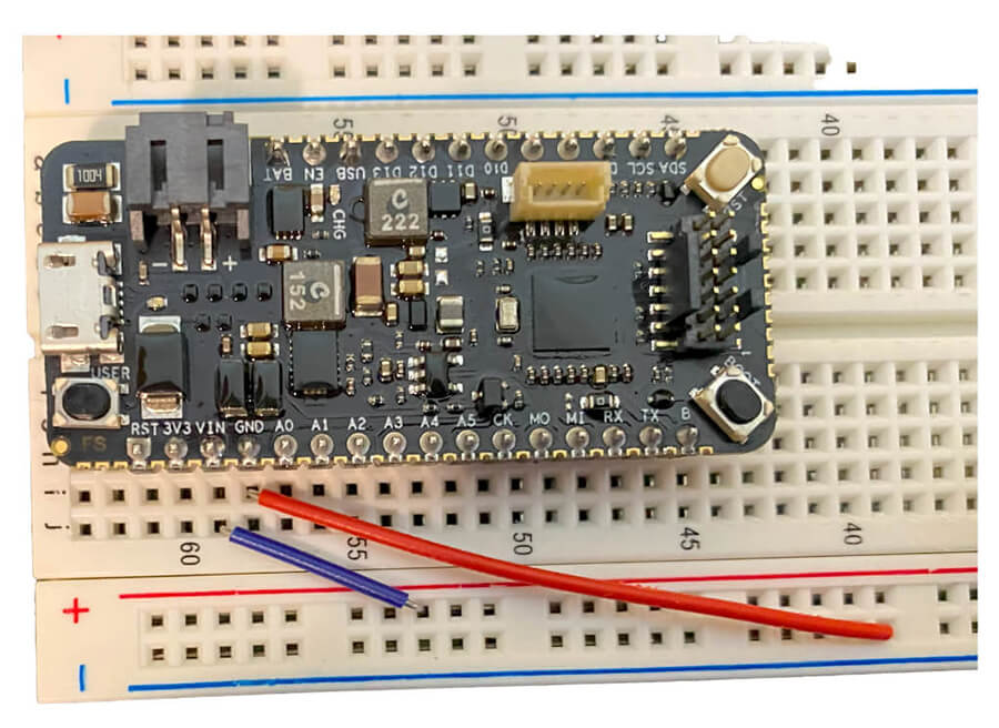
Once you've confirmed that the voltage is in an acceptable range, connect the
power to the development board's VIN pin. Similarly, connect the negative
rail to the GND pin. Since you're using a 5V power supply, you can connect
directly, like in the image below:
When you turn on your power supply, it powers up your development board. You can now link the development board to your computer or other device to program it.
The various pins on the Swan serve as inputs and outputs. For example, you might want to connect an environmental sensor (think along the lines of temperature, humidity, gas levels, pressure, etc) and read those values with the host microcontroller.
A great next step is to look at the Blues Starter Kit. With this kit and your own sensor you can start reading data to the host and syncing it with a cloud server over cellular!
Common Mistakes and Troubleshooting
Newcomers often encounter issues such as incorrect wiring, not using a current-limiting resistor with LEDs, or misplacing components in the wrong rows or columns.
Understanding polarity is crucial, especially with polarized components like LEDs and electrolytic capacitors. Polarity is the electrical current's direction, and semiconductors like LEDs only allow current to flow one way.
To determine polarity, check the lead length, as the LED's positive lead is
longer. Additionally, look for a notch cut out of an LED or a line printed on
a diode's housing, indicating the negative lead. An electrolytic capacitor may
have clipped leads, so check its polarity markings, + for positive and - for
negative. A multimeter can also help you determine a component's polarity.
A continuity tester, often found in multimeters, helps troubleshoot non-working circuits by checking if a component is receiving power. If not, check for loose connections, verify the component's orientation, and ensure the power is correctly supplying the board.
Beginners may also use the wrong voltage for their power source. Too much voltage can burn out your components, while too little voltage may prevent them from functioning. Always test your voltages to ensure you provide the correct amount of power for your circuit's requirements.
Conclusion
Mastering breadboarding is a rewarding skill that opens the door to endless exploration in electronics. As you become proficient, you'll find it easier to prototype, troubleshoot, and bring your electronic ideas to life.
This article if part of a broader series where you can dig deeper into each aspect of embedded development. To embark on this journey, be sure to follow Blues University, where you can explore and contribute to shaping the future of IoT. 💙