


In the traditional Arduino framework, code executes sequentially within a single setup() and loop() structure. The beauty of Arduino is its simplicity. However, there is an inflection point where the simplicity begins to introduce needless complexity. This complexity often presents itself when multiple peripherals require precise timing or polling, and it becomes difficult to manage everything within a single loop.
FreeRTOS significantly enhances the standard Arduino programming model by introducing a lightweight real-time operating system (RTOS). An RTOS enables true multitasking on resource-constrained microcontrollers, which allows multiple tasks to run concurrently with priority-based scheduling, context switching, and inter-task communication mechanisms like queues and semaphores.
In this article we’ll be converting an example from Arduino to FreeRTOS to show the difference between the two. Specifically, we’ll be converting the Example6_SensorTutorial sketch from the Blues Arduino Library. This sketch is the end result of the Blues sensor tutorial, and demonstrates a standard way to send sensor data to the cloud using a Blues Notecard.
Prerequisites
If you want to follow along with this article and run the examples yourself you’ll need to have Arduino IDE 2.x installed on your computer, as well as the Adafruit seesaw and Blues Wireless Notecard Arduino libraries.
To run the Arduino code you’ll additionally need the following hardware:
- Blues Cygnet or Swan MCU
- Blues Notecard (any variant)
- Blues Notecarrier-F
- Adafruit I2C QT Rotary Encoder
- USB cable
If you don’t have the prerequisites though don’t worry—you can still follow along even if you can’t run the examples.
And with that background out of the way, let’s start with the basics of how Arduino works.
Anatomy of an Arduino Sketch
As we all know, an Arduino sketch calls setup() once and loop() indefinitely.
void setup() {
    // this runs once
}
void loop() {
    // this runs indefinitely
}
But let's explore EXACTLY how that happens, so we can better understand how FreeRTOS changes that model.
At the end of the day, the Arduino API is just C++. And like all other C++ programs, your sketch MUST have a main() entrypoint. Let’s take a look at the main() entrypoint provided by the STM32duino board support package (BSP).
/*
 * \brief Main entry point of Arduino application
 */
int main(void)
{
  initVariant();

  setup();

  for (;;) {
#if defined(CORE_CALLBACK)
    CoreCallback();
#endif
    loop();
    serialEventRun();
  }

  return 0;
}
Looking at main(), it becomes clear why setup() executes once, and loop() goes on forever and ever. Interestingly, we can see a few more functions that are being called behind the scenes on our behalf, namely initVariant(), CoreCallback(), and serialEventRun().
It is important to understand the nature of these functions, because, depending on how our current application is implemented or the steps we take to migrate to FreeRTOS, we may need to replicate this functionality ourselves.
initVariant()
An extremely important function, which provides for variant-specific initializations (e.g. STM32L4R5, STM32L433, etc...). Pin and peripheral configurations are performed by this function, and it is absolutely critical that it runs.
CoreCallback()
Allows users to register custom callback functions that are executed prior to, or between each call to loop(). This offers an extension beyond standard Arduino APIs for more efficient event handling on STM32 boards.
serialEventRun()
A callback ensuring Serial::serialEvent is supported for backward compatibility with the deprecated Arduino API. This callback is functionally similar to CoreCallback(), but is integrated into the Arduino Serial API and single-purpose in nature.
Part 1: Introducing FreeRTOS
The easiest way to get started with FreeRTOS is to modify an existing application. As discussed earlier, in this article we’ll be using the Example6_SensorTutorial sketch from the Blues Arduino Library. If you’re following along, go ahead and open this sketch in Arduino IDE by selecting File --> Examples --> Blues Wireless Notecard --> Example6_SensorTutorial.
 note
noteIf you want to learn more about Example6_SensorTutorial, we have an in-depth breakdown in our Collecting Sensor Data tutorial.
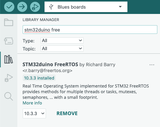
Installing FreeRTOS
Before you use FreeRTOS you need to install it. FreeRTOS implementations vary from platform to platform, so you will need to find a FreeRTOS that has been tailored to your system. Thanks to the Arduino Library Manager though, installing FreeRTOS support is extremely easy. Within Arduino IDE navigate to the Library Manager (see screenshot below), search for STM32duino FreeRTOS, and install it. That's it!
Code Changes
With the sketch open and STM32duino FreeRTOS installed, let’s start converting the code.
#include Headers
We've installed FreeRTOS, but now we need to access it from our program. Add the following #include statements to the top of your file.
// Include FreeRTOS API
#include <FreeRTOS.h>
#include <task.h>NOTE: The order is very important.
FreeRTOS.hmust appear in source files before includingtask.h, astask.hdepends on definitions fromFreeRTOS.h.
Owning the Run Loop
The run loop will reflect the most obvious change, because this is where we are able to introduce the most flexibility. Let’s begin with a simple adaptation from Arduino to FreeRTOS, by turning loop() into a task. To start, add the following function to your sketch.
// Create a long-running loop task to replace the ST main run loop
void loop_task (void *) {
  for (;;) {
#if defined(CORE_CALLBACK)
    CoreCallback();
#endif
    loop();
    serialEventRun();
  }
}
At this point, the code provided is nothing more than a function. (And it should look familiar, because it is the run loop from the ST implementation of main().)
In order to truly take ownership of the run loop, we need to launch this task and block the original run loop. That sounds like it might be hard, but FreeRTOS makes it easy.
Swap Platform APIs
To accommodate the inherently concurrent nature of an RTOS, we need swap a handful of platform APIs.
malloc-->pvPortMallocfree-->vPortFreedelay-->vTaskDelay
Fortunately, note-arduino has a method to update these platform APIs. Add a call to Notecard::setFn() just before you launch the scheduler (shown below).
Launch Multi-threaded Environment
Add the following lines to the end of your setup() function:
// Size of the task stack in "words" (a.k.a. `sizeof(int)`), not bytes.
static const int TASK_STACK_SIZE_WORDS = 1024;

// Launch `loop` in the FreeRTOS Scheduler
xTaskCreate(loop_task, "loop", TASK_STACK_SIZE_WORDS, NULL, 1, NULL);

// Set the platform APIs to thread-safe counterparts
// WARNING: MUST BE LAST STATEMENT BEFORE SCHEDULER INVOCATION
notecard.setFn(pvPortMalloc, vPortFree, vTaskDelay, millis);

vTaskStartScheduler(); // This never returns
The first line creates a constant TASK_STACK_SIZE_WORDS. Each FreeRTOS task has a certain amount of memory allocated to it, and everything it does must happen inside that footprint. The next line will create and queue the new loop_task function for execution. Then, we will swap the default platform APIs for their thread-safe counterparts. The final line starts the task scheduler, and the call to vTaskStartScheduler never returns and blocks any further execution.
That's it! Now we have transformed the original program into a task oriented, FreeRTOS application.
Task Termination
Now that we own the run loop, that means we have the ability to terminate the run loop. Who would want to do that!? Well, actually we do.
For example, look at the logic the current sketch has in place to stop sampling the sensor.
// Count the simulated measurements that we send to the cloud, and stop the
// demo before long.
static unsigned event_counter = 0;
if (++event_counter > 25)
{
    usbSerial.println("[APP] Demo cycle complete. Program stopped. Press RESET to restart.");
    delay(10000); // 10 seconds
    return;
}
Once the sensor has been sampled twenty-five times, it will begin to enter this if block, generate a log, wait ten seconds, exit loop() (which it immediately reenters), and repeats the process all over again. This results in spamming the log every ten seconds.
[APP] Demo cycle complete. Program stopped. Press RESET to restart.
[APP] Demo cycle complete. Program stopped. Press RESET to restart.
[APP] Demo cycle complete. Program stopped. Press RESET to restart.
...
If we replace the delay() and return with vTaskDelete(), then we can end the task and free the resources it is consuming, but no longer using.
// Count the simulated measurements that we send to the cloud, and stop the
// demo before long.
static unsigned event_counter = 0;
if (++event_counter > 25)
{
    usbSerial.println("[APP] Demo cycle complete. Program stopped. Press RESET to restart.");
    vTaskDelete(NULL); // Properly terminate task
}
Looking Back
Here’s what our application’s architecture looks like after this first part.
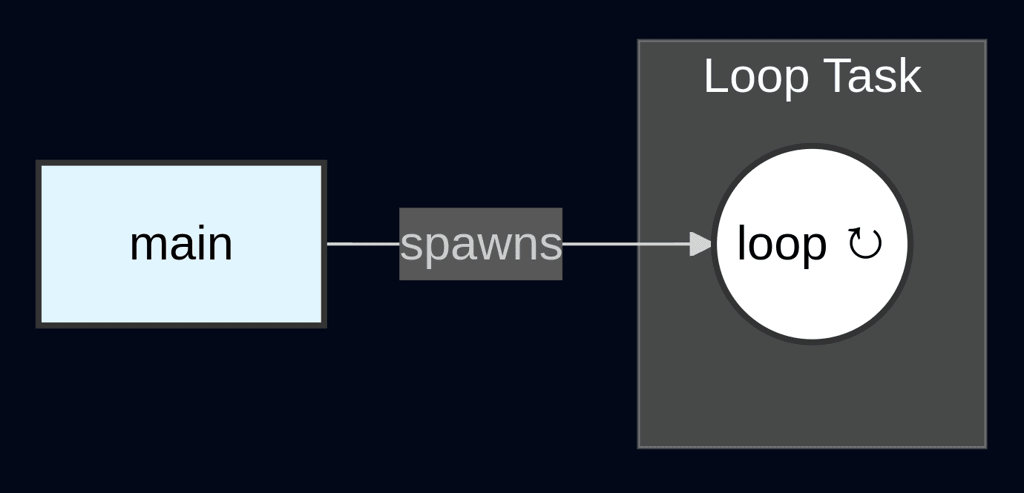
It’s fair to point out that we have added lines of code, but provided ZERO additional functionality.
But the program is now structured to leverage FreeRTOS, and the FreeRTOS framework provides the ability to create additional tasks, adjust priorities, and use inter-task communication mechanisms, which would not have been possible within the standard Arduino framework.
noteThe complete source code for the end of part 1 is available here.
Part 2: Application Decomposition
In this next part, we’ll take the tasks currently happening in our sketch’s loop() function and decompose them. The application is composed of two main activities:
- Sampling a sensor
- Sending the results to a Notecard
All this happens in loop(), so let's start by breaking these activities out into dedicated functions. Add the following two new functions to your sketch.
void sampleSensor (void *) {
    float temperature = sensor.temp();
    float humidity = sensor.humidity();

    usbSerial.print("[APP] Temperature = ");
    usbSerial.print(temperature);
    usbSerial.println(" *C");
    usbSerial.print("[APP] Humidity = ");
    usbSerial.print(humidity);
    usbSerial.println(" %");
}

void sendToNotecard (void *) {
    J *req = notecard.newRequest("note.add");
    if (req != NULL)
    {
        JAddStringToObject(req, "file", "sensors.qo");
        JAddBoolToObject(req, "sync", true);
        J *body = JAddObjectToObject(req, "body");
        if (body)
        {
            JAddNumberToObject(body, "temp", temperature);
            JAddNumberToObject(body, "humidity", humidity);
        }
        notecard.sendRequest(req);
    }
}
That was easy enough, but unfortunately it won't compile. The problem is that we need a way to share the data captured in the variables temperature and humidity between the two functions.
Data Structures
Let's start by defining a data structure, so the tasks understand how to decode our sensor data. Add the following struct to the top section of your sketch.
typedef struct {
    float humidity;
    float temperature;
} SensorData_t;
In a later step we’ll instantiate this struct. In a standard Arduino sketch, that instantiation would need to happen globally to both functions, or we would pass the values from one function to the next as parameters.
In the world of multi-threading, tasks operate completely independently of each other, so passing parameters is not an option. Global state can still work, but it can also be difficult to manage. To be successful, you must employ some mechanism to ensure one task doesn't read while another task is actively writing, otherwise you will end up with data corruption.
Message Queue
FreeRTOS has a primitive, called a queue, that captures the best of both worlds. FreeRTOS allows for data to be passed (as messages) between tasks via a queue. Unlike traditional global variables, the queue is purpose built with everything required to make it thread-safe—without the hassle described above.
To allow tasks to access the queue, we will instantiate the message queue globally. Start by adding #include <queue.h> to the top of your sketch.
// Include FreeRTOS API
#include <FreeRTOS.h>
#include <queue.h>
#include <task.h>
Next, add the following global variable declaration near the top of your sketch (next to Notecard notecard; is fine).
QueueHandle_t sensorQueue;Now that we have a message queue available, we need to initialize it with the appropriate length and size required by our application. To do so, add the following lines to your setup() function, before the task scheduler is invoked.
// Initialize message queue
static const int QUEUE_SIZE = 3;
sensorQueue = xQueueCreate(QUEUE_SIZE, sizeof(SensorData_t));The queue should only ever have a single entry, because we will only have one task producing data and one task consuming data. However, there may be a circumstance where communicating with Notecard becomes unstable. A queue size of size three provides three sampling intervals of time before data is lost.
Loop Modification
Now that we're moving into the world of threads, we can dismiss the concept of the Arduino loop, or at least a single loop that controls everything. It’s time to switch to a paradigm where we have multiple long-running tasks.
This means that, individually, each task will need to behave like main and execute indefinitely. To do so, let's take the following steps to modify our previously broken-out task functions to make them conform to the new paradigm:
-
Add an infinite loop so they individually become long-running tasks.
-
Utilize the message queue for inter-task communication.
-
Add a blocking call to control the loop. For
sampleSensorthis will bevTaskDelay(), and forsendToNotecardthis will bexQueueReceive().
First, replace your existing sampleSensor with the following:
void sampleSensor (void *) {
    static const TickType_t QUEUE_WAIT_TICKS = 0;
    static const size_t SAMPLING_INTERVAL = 15000;
    for (;;) {
        // Count the simulated measurements that we send to the cloud, and stop the
        // demo before long.
        static unsigned event_counter = 0;
        if (++event_counter > 25)
        {
            usbSerial.println("[APP] Demo cycle complete. Program stopped. Press RESET to restart.");
            vTaskDelete(NULL); // Properly terminate task
        }

        SensorData_t data;
        data.temperature = sensor.temp();
        data.humidity = sensor.humidity();

        usbSerial.print("[APP] Temperature = ");
        usbSerial.print(data.temperature);
        usbSerial.println(" *C");
        usbSerial.print("[APP] Humidity = ");
        usbSerial.print(data.humidity);
        usbSerial.println(" %");

        BaseType_t qErr = xQueueSend(sensorQueue, &data, QUEUE_WAIT_TICKS);
        if (qErr != pdPASS) {
            usbSerial.println("[APP|ERROR] FAILED TO QUEUE MESSAGE - SENSOR DATA PERMANENTLY LOST");
        }

        vTaskDelay(SAMPLING_INTERVAL); // block task
    }
}
sampleSensor should feel quite familiar, because the main control logic from loop now resides in this task. We can see both the fifteen second delay and the twenty-five loop limit. Beyond the infinite loop, we see the only other change is to use xQueueSend to share the data we've collected with the sendToNotecard task.
Next, replace your existing sendToNotecard function with the following:
void sendToNotecard (void *) {
    for (;;) {
        SensorData_t data;
        BaseType_t qErr = xQueueReceive(sensorQueue, &data, portMAX_DELAY);
        if (qErr != pdPASS) {
            usbSerial.println("[APP|WARN] Spurious timeout. Resuming queue wait...");
            continue;
        }

        J *req = notecard.newRequest("note.add");
        if (req != NULL)
        {
            JAddStringToObject(req, "file", "sensors.qo");
            JAddBoolToObject(req, "sync", true);
            J *body = JAddObjectToObject(req, "body");
            if (body)
            {
                JAddNumberToObject(body, "temp", data.temperature);
                JAddNumberToObject(body, "humidity", data.humidity);
            }
            notecard.sendRequest(req);
        }
    }
}
sendToNotecard didn't change much at all. Beyond its infinite loop, the only change is the blocking call to xQueueReceive that allows us to wait for any available sensor data from the message queue.
Scheduling Tasks
The final change will be to schedule our new tasks, similar to the way we scheduled loop_task.
In setup() where we originally scheduled our simple loop_task, we will make the following change from:
// FreeRTOS Scheduler
xTaskCreate(loop_task, "loop", TASK_STACK_SIZE_WORDS, NULL, 1, NULL);
vTaskStartScheduler(); // This never returns
To:
// FreeRTOS Scheduler
xTaskCreate(sampleSensor, "sample_sensor", TASK_STACK_SIZE_WORDS, NULL, 1, NULL);
xTaskCreate(sendToNotecard, "send_to_notecard", TASK_STACK_SIZE_WORDS, NULL, 1, NULL);
vTaskStartScheduler(); // This never returns
Housekeeping
Now that our task functions manage their own life-cycle, we can completely remove loop_task and empty the contents of loop—but not delete it, as loop MUST be present in Arduino applications.
void loop() {
    // empty
}
What Changed?
Here’s what the architecture looks like after the second part of our tutorial.
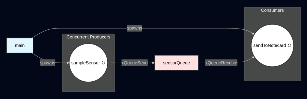
Once again, it is fair to point out that we have now significantly increased the complexity, yet we have still provided ZERO additional functionality from the original sketch.
However, we now have multiple fully independent and asynchronous tasks. These tasks are using the FreeRTOS message queue for thread-safe blocking and communication. We have now laid the foundation for a truly scalable application.
noteThe complete source code for the end of part 2 is available here.
Part 3: Application Expansion
In the final part of this tutorial, we’ll abstract our sensor implementation further, and then leverage that abstraction to add support for a new rotary sensor.
Sensor Abstraction
Let’s start by generalizing SensorData_t so it is capable of reflecting data from any sensor. But in order to do this, we will also need a way to describe each type of sensor data.
Replace the existing SensorData_t with the following:
enum class SensorType {
    HUMIDITY,
    TEMPERATURE
};

typedef struct {
    SensorType type;
    float value;
} SensorData_t;
Final Decomposition
The changes to our abstraction has broken the communication model between our tasks. To fix that, let’s decompose sampleSensor to conform to the new SensorData_t. Replace the existing sampleSensor function with the two new functions shown below.
void sampleHumidity (void *) {
    static const TickType_t QUEUE_WAIT_TICKS = 0;
    static const size_t SAMPLING_INTERVAL = 20000;
    for (;;) {
        // Count the simulated measurements that we send to the cloud, and stop the
        // demo before long.
        static unsigned event_counter = 0;
        if (++event_counter > 25)
        {
            usbSerial.println("[APP] Humidity demo cycle complete. Program stopped. Press RESET to restart.");
            vTaskDelete(NULL); // Properly terminate task
        }

        SensorData_t data;
        data.type = SensorType::HUMIDITY;
        data.value = sensor.humidity();

        usbSerial.print("[APP] Humidity = ");
        usbSerial.print(data.value);
        usbSerial.println(" %");

        BaseType_t qErr = xQueueSend(sensorQueue, &data, QUEUE_WAIT_TICKS);
        if (qErr != pdPASS) {
            usbSerial.println("[APP|ERROR] FAILED TO QUEUE MESSAGE - HUMIDITY DATA PERMANENTLY LOST");
        }

        vTaskDelay(SAMPLING_INTERVAL); // block task
    }
}

void sampleTemperature (void *) {
    static const TickType_t QUEUE_WAIT_TICKS = 0;
    static const size_t SAMPLING_INTERVAL = 15000;
    for (;;) {
        // Count the simulated measurements that we send to the cloud, and stop the
        // demo before long.
        static unsigned event_counter = 0;
        if (++event_counter > 25)
        {
            usbSerial.println("[APP] Temperature demo cycle complete. Program stopped. Press RESET to restart.");
            vTaskDelete(NULL); // Properly terminate task
        }

        SensorData_t data;
        data.type = SensorType::TEMPERATURE;
        data.value = sensor.temp();

        usbSerial.print("[APP] Temperature = ");
        usbSerial.print(data.value);
        usbSerial.println(" *C");

        BaseType_t qErr = xQueueSend(sensorQueue, &data, QUEUE_WAIT_TICKS);
        if (qErr != pdPASS) {
            usbSerial.println("[APP|ERROR] FAILED TO QUEUE MESSAGE - TEMPERATURE DATA PERMANENTLY LOST");
        }

        vTaskDelay(SAMPLING_INTERVAL); // block task
    }
}
Now we have two independent sensors, each having their own delay. This is subtle but important, because it models the fact that peripherals often have different warm up times and requirements. Tasks allow us to tailor isolated algorithms to meet those specific needs.
Now that we have dedicated tasks for each type of sensor task, we have to remember to swap the creation of the sampleSensor task.
Replace the following line:
xTaskCreate(sampleSensor, "sample_sensor", TASK_STACK_SIZE_WORDS, NULL, 1, NULL);With this:
xTaskCreate(sampleHumidity, "sample_humidity", TASK_STACK_SIZE_WORDS, NULL, 1, NULL);
xTaskCreate(sampleTemperature, "sample_temperature", TASK_STACK_SIZE_WORDS, NULL, 1, NULL);
More tasks also means more messages in the message queue. Let’s increase the value our buffer of three task to ten, so we can support more messages before data is lost.
// Initialize message queue
static const int QUEUE_SIZE = 10;
Processing Abstract Data
Next we will need to modify sendToNotecard to be able to process the new data format. To do so replace your sendToNotecard function with the updated version below.
void sendToNotecard (void *) {
    for (;;) {
        SensorData_t data;
        BaseType_t qErr = xQueueReceive(sensorQueue, &data, portMAX_DELAY);
        if (qErr != pdPASS) {
            usbSerial.println("[APP|WARN] Spurious timeout. Resuming queue wait...");
            continue;
        }

        J *req = notecard.newRequest("note.add");
        if (req != NULL)
        {
            switch(data.type) {
              case SensorType::HUMIDITY:
                JAddStringToObject(req, "file", "humidity.qo");
                break;
              case SensorType::TEMPERATURE:
                JAddStringToObject(req, "file", "temperature.qo");
                break;
              default:
                usbSerial.println("[APP|WARN] Unrecognized sensor reading");
            }

            JAddBoolToObject(req, "sync", true);
            J *body = JAddObjectToObject(req, "body");
            if (body)
            {
                JAddNumberToObject(body, "value", data.value);
            }
            notecard.sendRequest(req);
        }
    }
}
The main change is that we have separated the readings into dedicated queues. This allows us to collect and process information from each task individually. Doing so enables us to add new sensors and grow the scope of the application with minimal changes going forward.
Thread Safety
So far we have been able to steer clear of the hardest part of parallel programming: keeping our tasks working together harmoniously, by preventing race conditions and ensuring thread safety.
Semaphores
Before we begin to think about thread safety, we need to globally declare semaphores that can be used by the tasks for mutual exclusion in accessing the I2C bus and Notecard.
Start by adding #include <semphr.h> at the top of your sketch.
// Include FreeRTOS API
#include <FreeRTOS.h>
#include <queue.h>
#include <semphr.h>
#include <task.h>
Next add the following two declarations towards the top of your sketch.
SemaphoreHandle_t i2cMutex = NULL;
SemaphoreHandle_t notecardMutex = NULL;
And finally instantiate those values in your setup() function.
// Instantiate Semaphores for I2C and Notecard Mutexes
i2cMutex = xSemaphoreCreateMutex();
notecardMutex = xSemaphoreCreateMutex();
Notecard Task
Fortunately, Notecard’s Arduino library, note-arduino, supports thread-safety for both the Notecard object and the I2C bus. note-arduino has hooks used for managing mutexes around the I2C bus and the Notecard object. To leverage those hooks, we need to implement the callbacks required to make the mutexes consumable by the Notecard object.
Add the following functions to your sketch:
void lockI2c (void) {
    if (i2cMutex != NULL)
    {
        // Wait indefinitely for the mutex to become available
        for (;xSemaphoreTake(i2cMutex, portMAX_DELAY) != pdTRUE;);
    }
}

void unlockI2c (void) {
    if (i2cMutex != NULL)
    {
        xSemaphoreGive(i2cMutex);
    }
}

void lockNotecard (void) {
    if (notecardMutex != NULL)
    {
        // Wait indefinitely for the mutex to become available
        for (;xSemaphoreTake(notecardMutex, portMAX_DELAY) != pdTRUE;);
    }
}

void unlockNotecard (void) {
    if (notecardMutex != NULL)
    {
        xSemaphoreGive(notecardMutex);
    }
}
Finally, add these lines to setup() to register the mutex callbacks with the Notecard object, so it will be able to call them as needed.
// Register I2C and Notecard Mutexes
notecard.setFnI2cMutex(lockI2c, unlockI2c);
notecard.setFnNoteMutex(lockNotecard, unlockNotecard);
Now that we have configured the Notecard object with all the necessary components, we can trust it to manage its access to the I2C bus and attempts to access the Notecard object from multiple tasks.
Sensor Tasks
Next we have to address the thread safety of our sensors, and to do that we have to expose a dirty little secret: the PseudoSensor library this sketch uses gets its values by sending a request to Notecard, which in turn attempts to query attached sensors.
“Okay fine, but why are you telling me this?”
In theory, we have one task dedicated to speaking with Notecard, and the other tasks dealing with accumulating sensor data. However, due to the fact we are actually getting our sensor data from Notecard, we may inadvertently cause collisions if a sensor task happens to query Notecard while the Notecard task is attempting to queue data.
“Shouldn’t this have already happened during Part 2?”
Well, not quite. Even though the code in Part 2 had multiple tasks, they weren't actually independent from one another. The sendToNotecard task was gated on data being queued by the sampleSensor task. Therefore, the application actually interacted with Notecard in a serial fashion.
Luckily though, since our sensor values are coming from Notecard, their thread safety has already been accommodated by the changes we put in place for the Notecard task. No additional work is required.
Adding a New Sensor
Now that we have successfully abstracted sensor readings and their processing, it will be simple to add another sensor.
The next sensor we will use to collect data will be the Adafruit Rotary Encoder. We picked this sensor because it’s Qwiic-compatible (so easy to plug into any Notecarrier), and because Adafruit has ready-made libraries we can easily add.
New Sensor Type
To add this new sensor to our firmware, first we must add another type to our SensorType enum:
enum class SensorType {
    ENCODER,
    HUMIDITY,
    TEMPERATURE
};
New Sensor Task
Next, let’s add a new task to sample the Adafruit Rotary Encoder.
Start by installing the Adafruit seesaw Library, and adding the necessary #include to the top of your sketch.
// Include Adafruit seesaw Library
#include <Adafruit_seesaw.h>
After that, declare the sensor’s object in the global scope near the Notecard object.
Adafruit_seesaw ss;Then let’s implement the new task that will allow us to sample the encoder.
void sampleEncoder (void *) {
    static const TickType_t QUEUE_WAIT_TICKS = 0;
    static const size_t SAMPLING_INTERVAL = 30000;
    static const unsigned int SEESAW_ADDR = 0x36;

    // Initialize seesaw
    lockI2c();
    if (!ss.begin(SEESAW_ADDR)) {
        usbSerial.println("[APP|ERROR] FAILED TO DETECT SEESAW AT PROVIDED ADDRESS!");
        unlockI2c();
        vTaskDelete(NULL); // Properly terminate task
    }
    unlockI2c();

    for (;;) {
        // Count the simulated measurements that we send to the cloud, and stop the
        // demo before long.
        static unsigned event_counter = 0;
        if (++event_counter > 25)
        {
            usbSerial.println("[APP] Encoder demo cycle complete. Program stopped. Press RESET to restart.");
            vTaskDelete(NULL); // Properly terminate task
        }

        SensorData_t data;
        data.type = SensorType::ENCODER;
        lockI2c();
        data.value = ss.getEncoderPosition();
        unlockI2c();

        usbSerial.print("[APP] Encoder position = ");
        usbSerial.println(data.value);

        BaseType_t qErr = xQueueSend(sensorQueue, &data, QUEUE_WAIT_TICKS);
        if (qErr != pdPASS) {
            usbSerial.println("[APP|ERROR] FAILED TO QUEUE MESSAGE - ENCODER DATA PERMANENTLY LOST");
        }

        vTaskDelay(SAMPLING_INTERVAL); // block task
    }
}
This task speaks directly with the encoder over I2C. Remember the I2C bus is also used to speak with our Notecard. In parallel programming this presents us with a race-condition, because any of the tasks may attempt to use the I2C bus at any time.
We have already provided the Notecard object with necessary tools to prevent collisions, but our new task also needs to take steps to manage sharing the I2C bus. If we inspect our sensor task closely, we will see there are only two places we expect it to use the I2C bus: once during setup, and once with each sampling of the sensor.
The setup happens once at the very beginning of the program (outside the run loop).
// Initialize seesaw
lockI2c();
if (!ss.begin(SEESAW_ADDR)) {
    usbSerial.println("[APP|ERROR] FAILED TO DETECT SEESAW AT PROVIDED ADDRESS!");
    unlockI2c();
    vTaskDelete(NULL); // Properly terminate task
}
unlockI2c();
The sampling occurs in a single line of our sensor task code (when we set data.value), so we surround only that line with the logic required to take the mutex.
lockI2c();
data.value = ss.getEncoderPosition();
unlockI2c();
You’ll notice we were able to reuse the callbacks we provided to the Notecard object by calling them directly. This is not strictly necessary, but it is convenient since we wish to use the mutexes in the same fashion as they are being used by the Notecard object.
noteIt is important to minimize the lines of code executed while holding the mutex. This is known as the critical section. The smaller the critical section, the more your application can benefit from parallel processing.
Processing the New Data
Now that we are capturing the new value, we need to teach the sendToNotecard() task how to process it. Let’s add the new SensorType::ENCODER to the switch statement:
switch(data.type) {
    case SensorType::ENCODER:
        JAddStringToObject(req, "file", "encoder.qo");
        break;
    case SensorType::HUMIDITY:
        JAddStringToObject(req, "file", "humidity.qo");
        break;
    ...
Scheduling the New Task
Finally, we add the new task to the list of tasks ready for the scheduler in setup().
// FreeRTOS Scheduler
xTaskCreate(sampleEncoder, "sample_encoder", TASK_STACK_SIZE_WORDS, NULL, 1, NULL);
xTaskCreate(sampleHumidity, "sample_humidity", TASK_STACK_SIZE_WORDS, NULL, 1, NULL);
xTaskCreate(sampleTemperature, "sample_temperature", TASK_STACK_SIZE_WORDS, NULL, 1, NULL);
xTaskCreate(sendToNotecard, "send_to_notecard", TASK_STACK_SIZE_WORDS, NULL, 1, NULL);
vTaskStartScheduler(); // This never returns
And that’s it! Because we have already done the upfront work to abstract sensor tasks, we can grow and scale our application with minimal effort.
Final Form
Here’s the updated architecture of our firmware after the changes we made in part 3.
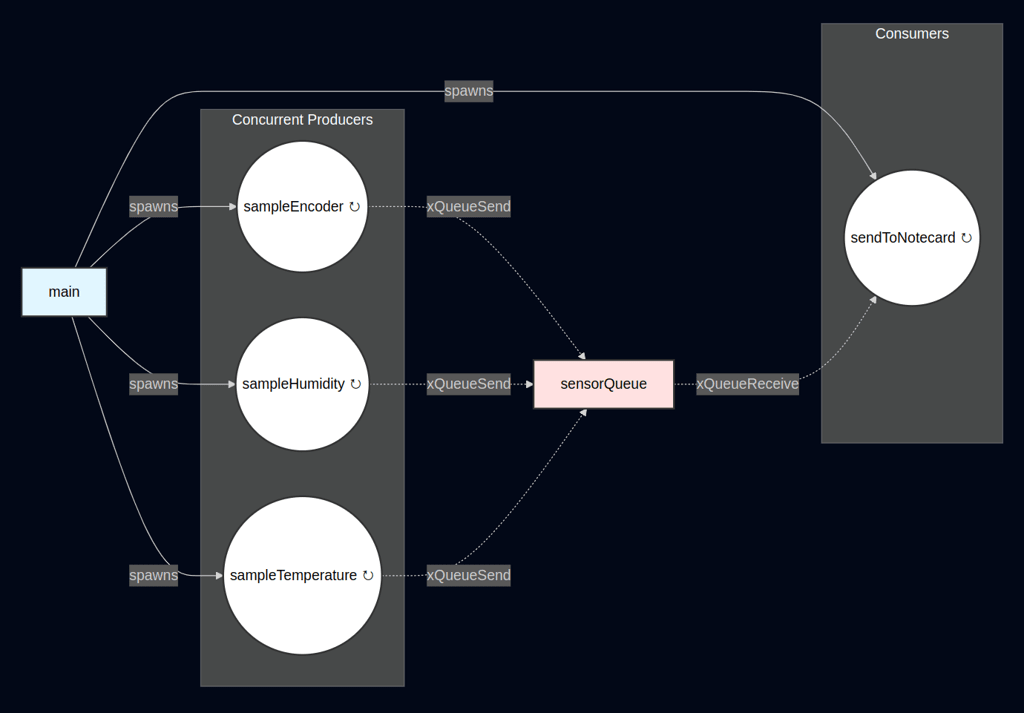
We now have multiple concurrent tasks producing sensor data. All samples are collected independently and stored in the message queue. From there, the sendToNotecard task is able to consume each sample, in a thread-safe manner, and forward them on to Notecard.
We have a fully scalable application architecture that makes adding new sensors simple!
noteThe complete source code for the end of part 3 is available here.
Summary
You have now have integrated FreeRTOS, a lightweight real-time operating system, into the Arduino framework to enhance multitasking capabilities on resource-constrained microcontrollers.
By adding FreeRTOS headers, transforming the loop() into a task, and using a scheduler, you have decomposed the application into independent tasks for sampling sensors and sending data, with a thread-safe message queue sharing temperature and humidity data.
Sensor data was abstracted into a SensorData_t structure with a SensorType enum for scalability, while semaphores (i2cMutex and notecardMutex) used in conjunction with the note-arduino mutex hooks ensured thread-safe I2C and Notecard access.
Finally, adding a new sensor highlighted the approach’s scalability, establishing a robust foundation for multitasking Arduino applications despite the initial added complexity.