Putting a Host to Sleep Between Sensor Readings
Introduction
This sample app demonstrates how to build projects that periodically take sensor readings, and use the Notecard to put a host MCU to sleep for a set period between readings. This approach is useful in low-power applications, where minimizing energy consumption is essential for prolonging battery life.
Wireless Connectivity with Blues
This sample app is built around the Blues Notecard and Blues Notehub.
The Blues Notecard is the easiest way for developers to add secure, robust, and affordable pre-paid wireless connectivity to their microcontroller or single-board computer of choice. Notecard is a System-on-Module (SoM) that combines pre-paid data, low-power hardware (~8μA-18μA when idle), and secure communications. It acts as a device-to-cloud data pump to communicate with the Blues cloud service Notehub.
Notehub is the Blues cloud service for routing Notecard-provided data to third-party cloud applications, deploying OTA firmware updates, and securely managing fleets of Notecards. Notehub allows for secure communications between edge devices and the cloud without certificate management or manual provisioning of devices.
General Information
System Hardware
This article’s pattern can be implemented with any Notecard, any host microcontroller, any sensor, and any battery. For demonstration purposes, this article uses the following hardware.
| Component | Purpose |
|---|---|
| Blues Notecard Cell+WiFi WBGLWT | Wireless connectivity module enabling device-to-cloud data syncing. |
| Blues Notecarrier F | Carrier board for connecting Notecard to an MCU. |
| Blues Swan | Example host MCU. |
| Adafruit SCD-40 | Example sensor. |
| LiPo Battery | Power source. |
This article also shows how to implement a deep-sleep variant of the pattern using a Blues Notecarrier CX, which has its STM32 host onboard.
List of Acronyms
| Acronym | Definition |
|---|---|
| MCU | Microcontroller |
| SoM | System-on-Module |
Summary
The Notecard greatly simplifies the process of building low-power, sensor-based applications. In addition to being a SoM that's low power by nature (idling at ~8μA-18μA), the Notecard additionally has the ability to manage the power of a host microcontroller and its connected sensors.
As MCUs and sensors are often the biggest sources of power consumption in embedded projects, using the Notecard to intelligently manage these components can drastically reduce the power consumption of your devices.
Requirements
-
A host MCU that either exposes its own enable (
EN) pin, or supports a low-power mode that a GPIO interrupt can wake it from (for example, STOP2 on the Notecarrier CX's STM32 host). -
One or more sensors that are powered by the same host MCU.
-
Host firmware that takes readings from your sensor(s), and uses the Notecard API to put the MCU to sleep or into a low-power mode.
Technical Implementation
Choosing a Sleep Mechanism
This example uses the Notecard's ATTN pin to decide when the host sleeps and
when it wakes. The host asks the Notecard to pull ATTN low with a
card.attn
sleep request, and the Notecard raises ATTN again after a timeout or
another wake condition. What ATTN is wired to on the host side determines
what "sleep" means:
| Mechanism | Wire ATTN to | What happens while asleep | Use with |
|---|---|---|---|
| Power gating | The host MCU's own enable pin (for example, the EN pin on a Feather) | The host and anything powered from its rail are fully powered off. The host cold-boots on wake. | Notecarrier F (via the FEATHER_EN DIP switch), or any host MCU with its own enable pin on its own power rail. |
| Deep sleep with ATTN wake | A GPIO pin on the host | The host enters its deepest interrupt-capable low-power mode (STOP2 on STM32, a few µA) and resumes in place on the ATTN rising edge. | Notecarrier CX, or any host that shares a power rail with the Notecard. |
 warning
On the Notecarrier CX,
EN enables the 3.3V VIO rail shared by the onboard STM32 host and the
Notecard's I/O. The CX's ATTN and EN pins are not connected to each
other, and connecting them does not put the host to sleep: when the Notecard
pulls ATTN low the rail drops, ATTN is left undriven, the rail comes
back, and the cycle repeats every few seconds. Use the
deep sleep pattern on the CX.
Hardware Wiring
Power Gating
With the power gating approach, you need to wire the Notecard's ATTN
pin to your host MCU's enable pin.
| Notecard | Host MCU |
|---|---|
ATTN | EN |
Additionally, before continuing ensure your host is connected to battery power and any sensor you intend to use.
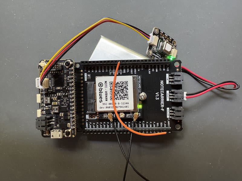
The demonstration hardware for this example (Cellular Notecard, Notecarrier F, Blues Swan, SCD40 sensor, 2000mAh LiPo battery), is shown connected below.
 note
noteIf you're using a Notecarrier F, you can optionally set the
FEATHER_EN DIP switch
to N_ATTN instead of manually wiring the Notecard's ATTN pin to your host's
enable pin.
Deep Sleep With ATTN Wake (Notecarrier CX)
With the deep-sleep approach, you need to wire the Notecard's ATTN pin to a
free GPIO on the host. Both pins are on the same 16-pin header of the
Notecarrier CX; this example uses D5.
| Notecarrier CX | Notecarrier CX |
|---|---|
ATTN | D5 |
Any interrupt-capable GPIO works if D5 is taken by a sensor; change ATTN_PIN
in the firmware to match.
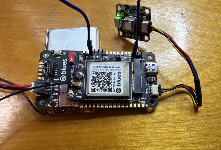
The demonstration hardware for this variant (Cellular Notecard, Notecarrier CX, SCD40 sensor on the Qwiic port, LiPo battery, is shown connected below.
Notecard Configuration
 tip
tipLet AI write your firmware. Blues Expert MCP connects your AI coding assistant (Claude Code, GitHub Copilot, Cursor) directly to our API docs, providing live request validation and firmware best practices for Arduino, C, Zephyr, and Python. Install the Blues Expert MCP →
Every Notecard must be associated with a cloud-based Notehub project. This is accomplished using the hub.set API.
The request below shows a typical configuration for a low-power application that uses periodic synchronization mode, and uses voltage-variable values for the outbound and inbound intervals. You can take this configuration verbatim, or switch up the intervals based on your project's needs.
{
  "req":"hub.set",
  "product": "<your-product-uid>",
  "mode":"periodic",
  "voutbound":"usb:10;high:60;normal:120;low:360;dead:0",
  "vinbound":"usb:10;high:1440;normal:1440;low:1440;dead:0"
}J *req = NoteNewRequest("hub.set");
JAddStringToObject(req, "product", "<your-product-uid>");
JAddStringToObject(req, "mode", "periodic");
JAddStringToObject(req, "voutbound", "usb:10;high:60;normal:120;low:360;dead:0");
JAddStringToObject(req, "vinbound", "usb:10;high:1440;normal:1440;low:1440;dead:0");
NoteRequest(req);req = {"req": "hub.set"}
req["product"] = "your-productuid"
req["mode"] = "periodic"
req["voutbound"] = "usb:10;high:60;normal:120;low:360;dead:0"
req["vinbound"] = "usb:10;high:1440;normal:1440;low:1440;dead:0"
card.Transaction(req)For the voltage-variable values to work, the Notecard must know what power source you plan to use (so it knows whether a voltage reading is "usb", "high", "normal", "low", or "dead").
You can provide this information with the card.voltage API. The request below
shows how to tell the Notecard you're using a LiPo battery, and you can refer to
the request's API documentation
for a list of the other available values.
{
  "req":"card.voltage",
  "mode":"lipo"
}J *req = NoteNewRequest("card.voltage");
JAddStringToObject(req, "mode", "lipo");
NoteRequest(req);req = {"req": "card.voltage"}
req["mode"] = "lipo"
rsp = card.Transaction(req)Host Firmware
noteThe full sample host firmware for both variants is available on GitHub: power gating (Notecarrier F + Swan) and deep sleep with ATTN wake (Notecarrier CX). You may wish to refer to the full source code as you read through this section.
The firmware running on the host MCU is responsible for taking sensor
readings, queuing a Note on the Notecard with the sensor values, and
then using the Notecard's card.attn command to request that the host
be put to sleep.
The firmware in this section uses the Notecard's Arduino library, but you can implement this pattern with any of the Notecard's SDKs.
The structure of the firmware depends on which sleep mechanism your hardware uses, so this section shows both. The sensor code is the same either way, so it's shown first as a set of helper functions that both variants call.
Sensor Helpers
These helpers are specific to the SCD40 used in this example. If you're using
a different sensor, replace the bodies of setupSensor() and
readFromSensor() with your own sensor logic and keep the same shape:
initialize once, then take one reading per wake.
setupSensor() initializes the I2C bus and the SCD40 driver.
readFromSensor() takes a single reading: it starts the sensor's periodic
measurement mode, waits for the first sample, reads it, and stops measurement
again so the sensor idles at its lowest power. queueReading() adds the values
to a Note on the Notecard.
#include <SensirionI2cScd4x.h>
#include <Wire.h>

SensirionI2cScd4x scd4x;

struct Reading
{
  uint16_t co2;
  float temp;
  float humidity;
};

void setupSensor()
{
  Wire.begin();
  scd4x.begin(Wire, SCD40_I2C_ADDR_62);

  // The sensor may still be in periodic-measurement mode from before a
  // reset, and it NACKs a second start. Stop it, and give it the 500 ms
  // the datasheet requires before it accepts another command.
  scd4x.stopPeriodicMeasurement();
  delay(500);
}

// Returns true and fills `reading` on success.
bool readFromSensor(Reading &reading)
{
  int16_t error;
  char errorMessage[256];

  error = scd4x.startPeriodicMeasurement();
  if (error) {
    Serial.print("Error trying to execute startPeriodicMeasurement(): ");
    errorToString(error, errorMessage, 256);
    Serial.println(errorMessage);
    scd4x.stopPeriodicMeasurement(); // in case it was already running
    return false;
  }

  Serial.println("Waiting for first measurement... (5 sec)");
  delay(5000);

  error = scd4x.readMeasurement(reading.co2, reading.temp, reading.humidity);
  bool ok = true;
  if (error) {
    Serial.print("Error trying to execute readMeasurement(): ");
    errorToString(error, errorMessage, 256);
    Serial.println(errorMessage);
    ok = false;
  } else if (reading.co2 == 0) {
    Serial.println("Invalid sample detected, skipping.");
    ok = false;
  } else {
    Serial.print("Co2:");
    Serial.print(reading.co2);
    Serial.print("\t");
    Serial.print("Temperature:");
    Serial.print(reading.temp);
    Serial.print("\t");
    Serial.print("Humidity:");
    Serial.println(reading.humidity);
  }

  error = scd4x.stopPeriodicMeasurement();
  if (error) {
    Serial.print("Error trying to execute stopPeriodicMeasurement(): ");
    errorToString(error, errorMessage, 256);
    Serial.println(errorMessage);
  }

  return ok;
}

void queueReading(const Reading &reading)
{
  J *req = notecard.newRequest("note.add");
  if (req != NULL)
  {
    JAddStringToObject(req, "file", "data.qo");
    J *body = JAddObjectToObject(req, "body");
    if (body)
    {
      JAddNumberToObject(body, "co2", reading.co2);
      JAddNumberToObject(body, "temp", reading.temp);
      JAddNumberToObject(body, "humidity", reading.humidity);
    }
    notecard.sendRequest(req);
  }
}
Power-Gating Firmware
With power gating, the host cold-boots every time the Notecard turns it back
on, so the reading happens in setup().
void setup()
{
  ...

  // Turn on the Swan's onboard LED when it's powered on. This is a handy
  // trick during development as you'll have a visual signal when your host
  // is powered on.
  pinMode(LED_BUILTIN, OUTPUT);
  digitalWrite(LED_BUILTIN, HIGH);

  setupSensor();

  Reading reading;
  if (readFromSensor(reading))
  {
    queueReading(reading);
  }
}
Note that all of the code above is in the Arduino setup() function,
which is normally intended to only run once when the MCU is powered on.
However, when using this article's pattern the setup() function runs every
time the host is powered back on by the Notecard. Because of this, the
code in the Arduino loop() function is minimal.
void loop()
{
  // Request that the Notecard place the host to sleep. Use a "command"
  // instead of a "request" because the host is going to power down and
  // cannot receive a response.
  J *req = notecard.newCommand("card.attn");
  JAddStringToObject(req, "mode", "sleep");
  JAddNumberToObject(req, "seconds", 3600);
  notecard.sendRequest(req);

  // Delay 1 second in case the host fails to sleep and try again
  delay(1000);
}
This code invokes the Notecard's
card.attn request
to instruct the Notecard to power down the host.
By using the seconds argument, you tell the Notecard the interval
at which the Notecard should power the host back on, in this case
3600 seconds, or 1 hour.
With this pattern in place, you allow the Notecard to idle in a low-power mode with the host and sensor(s) completely powered off. Then, every hour (or whatever interval you configure), you turn on the host to take a new reading before returning to a low-power state.
noteThe card.attn request offers several different triggers you can use to
wake up a host (not just seconds). For example, you can wake a host when
the Notecard receives an inbound Note, when the Notecard moves (as detected
by its onboard accelerometer), or when environment variables change.
For a full list of the options available, check out the
card.attn request's API documentation.
noteDuring development, you cannot flash firmware if your host is disabled via its
EN pin.
The easiest way to re-enable your host is by removing the connection between
the Notecard's ATTN pin and your host's EN pin.
If you're using a Notecarrier F, you can also set the FEATHER_EN DIP switch
to ON to enable your host, and then flip the switch back to N_ATTN
after you finish flashing firmware.
Deep-Sleep Firmware (Notecarrier CX)
On the Notecarrier CX the host stays powered, so the firmware itself has to
enter a low-power mode and arrange to be woken by ATTN. The
STM32LowPower library (install
STM32duino Low Power and its dependency STM32duino RTC from the
Arduino Library Manager) provides both halves: LowPower.deepSleep() enters
STOP2, and LowPower.attachInterruptWakeup() registers the pin that ends it.
warningBuild with Tools > USB support (if available) set to None, not the
CDC setting the Notecarrier CX quickstart uses. With the USB device stack
running and no USB host attached (battery power, or the USB-C switch set to
NC), the STM32's USB wakeup interrupt fires continuously and the host leaves
STOP2 within a millisecond of entering it. If you need USB serial during
bring-up, call Serial.end() before LowPower.deepSleep() and
Serial.begin() after it instead.
Because the host resumes in place rather than cold-booting, the firmware takes
the familiar Arduino shape: setup() runs once, and loop() takes a reading,
queues a Note, and sleeps, using the same
sensor helpers as the power-gating version.
#include <Notecard.h>
#include <STM32LowPower.h>

// Host pin the Notecard's ATTN line is jumpered to.
#define ATTN_PIN D5
#define SLEEP_SECONDS 1800 // 30 minutes

Notecard notecard;

// Nothing to do in the ISR: waking up is the side effect.
static void onAttnRising() {}

void setup()
{
  // Turn on the onboard LED whenever the host is awake. This gives you a
  // visual signal of when the host is sleeping during development.
  pinMode(LED_BUILTIN, OUTPUT);
  digitalWrite(LED_BUILTIN, HIGH);

  // ATTN is driven push-pull by the Notecard, so no pull resistor is needed
  // (and one would leak current against it).
  pinMode(ATTN_PIN, INPUT);

  notecard.begin();

  ... // hub.set and card.voltage, as in the Notecard Configuration section

  setupSensor();

  // Wake from STOP2 on the ATTN rising edge.
  LowPower.begin();
  LowPower.attachInterruptWakeup(ATTN_PIN, onAttnRising, RISING, DEEP_SLEEP_MODE);
}

void loop()
{
  Reading reading;
  if (readFromSensor(reading))
  {
    queueReading(reading);
  }

  sleepUntilAttn(SLEEP_SECONDS);
}
The sleep itself is a short function. It sends the same card.attn sleep
request as the power-gating version, with two differences. Because the host
stays alive, it can use a request instead of a command and check the result,
which matters right after a cold boot when the Notecard may not be ready yet.
And it waits for ATTN to actually go low before sleeping; otherwise the
rising edge the host is waiting for could already have happened.
// Ask the Notecard to hold ATTN low for `seconds`, then sleep until it rises.
static void sleepUntilAttn(uint32_t seconds)
{
  J *req = notecard.newRequest("card.attn");
  JAddStringToObject(req, "mode", "sleep");
  JAddNumberToObject(req, "seconds", seconds);
  if (!notecard.sendRequestWithRetry(req, 5))
  {
    // The Notecard isn't ready yet; try again on the next loop.
    return;
  }

  // Don't sleep until ATTN has gone LOW.
  unsigned long start = millis();
  while (digitalRead(ATTN_PIN) == HIGH && (millis() - start) < 5000)
  {
    delay(10);
  }
  if (digitalRead(ATTN_PIN) == HIGH)
  {
    // ATTN isn't reaching the host. Check the ATTN -> D5 jumper.
    return;
  }

  digitalWrite(LED_BUILTIN, LOW);

  // If you're logging over a UART, flush it and give its final TX interrupt
  // ~10 ms to fire first; entering STOP2 with that interrupt pending makes
  // deepSleep() return immediately.

  // STOP2 until the ATTN rising edge. Execution resumes on the next line.
  LowPower.deepSleep();

  digitalWrite(LED_BUILTIN, HIGH);
}
With this pattern in place, the host draws a few microamps between readings,
its RAM is preserved, and the Notecard decides when it wakes, so every
card.attn wake condition (a timeout, inbound Notes, motion, environment
variable changes) works exactly as it does with power gating.
noteIf all you need is a fixed interval, the host's own RTC could wake it without
involving the Notecard. card.attn is the better choice when the Notecard
should decide when the host wakes: its clock is network-synced, the interval
can be tuned from Notehub with an environment variable, and the same wiring
supports event-driven wakes.
noteWith USB support set to None there is no USB serial on the host. While developing this pattern, log through an STLINK instead; see Serial Logging With STLINK.
