
Collecting Sensor Data
C/C++ (STM32Cube), STM32 Discovery, and Notecarrier A
Don't see your favorite hardware here? Rest assured the Notecard works with virtually every MCU and SBC available. If you can't figure out how to complete this tutorial let us know in our forum and we can help you out.
Introduction
This tutorial should take approximately 40-50 minutes to complete.
In this tutorial, you'll learn how to take sensor readings from a Device and send readings to your Notecard and the Blues Notehub. You'll use C/C++ (STM32Cube) running on a STM32 Discovery wired up to Notecarrier A hardware. If you would like to use a different language, board, or Notecarrier, modify the dropdowns at the top of this guide. And if you get stuck at any point, the full source code for each example is available on GitHub.
Set up Hardware
First, you'll need to get all of your hardware connected. Follow the instructions below to connect your STM32 Discovery and Notecard mounted on a Notecarrier A.
In order to complete this guide, you'll need the following:
- A Notecard mounted to Notecarrier A.
- Any STM32 Discovery board with STMod+ Fan-Out Expansion Board. This guide uses the STM32L4P5AG. If you use a different board, make sure to adapt the pin configuration instructions below to your specific board.
- Micro USB to USB-A cable.
- Your sensor of choice. This guide uses the Seeed Grove BME680. You're welcome to use any sensor and adapt the code in this guide to read from it instead.
- 4 male/male jumper wires.
- The STM32CubeIDE. ST provides installers for all major OSes. The IDE is free, provided you create an account at ST.com.
Connect the sensor to your STM32 Discovery
Connect the BME680 Breakout to the Seeed Studio™ Grove I2C connector on the STMod+ Fan-Out Expansion Board.

Connect the STM32 Discovery to your Notecarrier A
Now connect to your Notecarrier A to your STMod+ Fan-Out Expansion Board using the I2C bus.
- Connect
V+from the Notecarrier A to the5Vpin on the STMod+ Fan-Out Expansion Board. - Connect
GNDfrom the Notecarrier A to aGNDpin on the STMod+ Fan-Out Expansion Board. - Connect
SCLfrom the Notecarrier A to the7/SCL(PF14) pin on the STMod+ Fan-Out Expansion Board. - Connect
SDAfrom the Notecarrier A to the10/SDA(PF15) pin on the STMod+ Fan-Out Expansion Board.

Official STM32L4P5AG Discovery Kit Documentation
Create a Notehub Project
Now that your hardware is all connected, let's create a new Notehub project to receive sensor readings from your Notecard.
-
Navigate to notehub.io and log-in, or create a new account.
-
Using the New Project card, give your project a name and ProductUID.
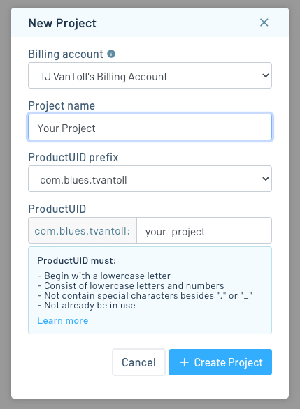
 note
noteThe ProductUID must be globally unique, so we recommend a namespaced name like
"com.your-company.your-name:your_product". -
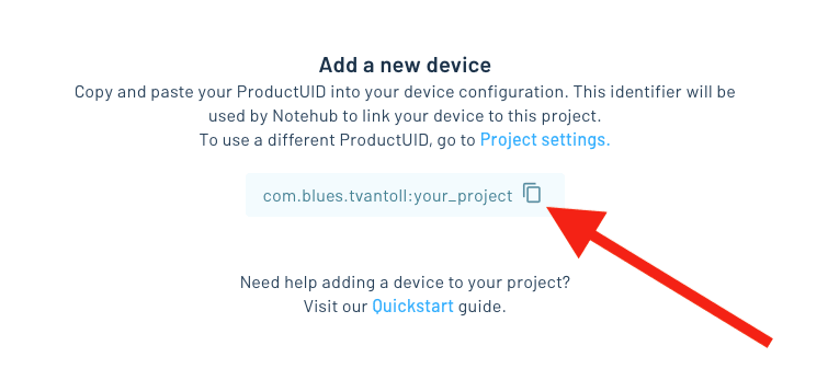
Take note of your ProductUID. This identifier is used by Notehub to associate your Notecard to your project.
Write Firmware
Create a new STM32CubeIDE Project
Additional Linux Setup
The Linux installer does not install all dependencies required by the
STM32CubeIDE. You will need to manually install libncurses5,
or you will receive the following error when you attempt to flash your code.

noteBefore selecting to create a new project, you may wish to move either this tutorial, or the IDE, to another desktop. If not, the following pop-up menus will display over the top of this tutorial.
-
Open the STM32CubeIDE and select File > New > STM32 Project. It may take a few minutes while the IDE downloads some required dependencies.

-
In the STM32 Project dialog, click the Board Selector tab.

-
In the Part Number Search box, enter "STM32L4P5" (or your dev board part number, if different).

-
Select the board from the list and click the Next button (appears bottom/right -- below screenshot area).

-
Give your project a name (for example,
stm32-sensor-tutorial-with-library), and specify a location to save the files. Keep the remaining defaults and click Finish.
-
Click Yes in the "Initialize all peripherals with their default Mode?" dialog.

-
Click Yes when prompted with the "Open Associated Perspective?" dialog, to switch to the "Device Configuration Tool perspective."
Configure the STM32 Discovery Pinout
Once your project is loaded in the STM32CubeIDE, the project will load the
Device Configuration Tool, which you'll use to define how the GPIO pins on
the STM32 Discovery board should function. If this perspective doesn't load
automatically, double-click on the *.ioc file in your project to load it.

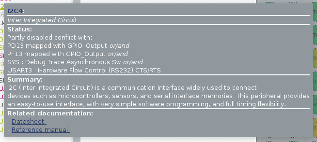
The STM32 Discovery board features several I2C peripherals. Before you attempt to configure the pinout, you must know which peripherals you will be working with. The STMod+ Fan-Out Expansion Board provides the easiest path forward, so it is important to understand which peripherals service it.

As shown above, the I2C4 peripheral must be configured for use with the STMod+
Fan-Out Expansion Board. Unfortunately, the default peripheral initialization
leaves the I2C4 peripheral in a paritally disabled state, as shown below.

Configure I2C Pins
Before you can communicate with either the Notecard or the BME680, you will need
to enable the I2C4 peripheral by addressing the warning messages provided by
the STM32CubeIDE.
To clear the warning, click on the pin labeled PF13, then in the drop-down
that appears, select Reset_State.

Configure USART Pins
While not strictly necessary, enabling the USART2 peripheral will allow logging messages to be delivered directly to the console. You can enable the USART2 peripheral by addressing the warning messages provided by the STM32CubeIDE.
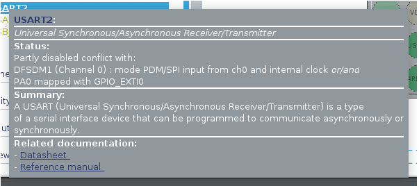
Click on the pin labeled PA0, then in the drop-down that appears, select
Reset_State.

Generate MCU Firmware
-
Now, select File > Save from the menu bar (
Ctrl+S). -
Click Yes in the "Do you want to generate Code?" dialog. At this point, STM32CubeIDE will generate the code to configure the GPIO functions of your STM32 Discovery board as specified.

-
Click Yes when prompted with the "Open Associated Perspective?" dialog, to switch to the "C/C++ perspective."
Customize MCU Firmware
Add note-c to Project
The easiest way to communicate with the Notecard from the STM32 Nucelo is with
the note-c library.
-
Clone or download the
note-clibrary from its GitHub Repo. -
Copy the complete contents of the library into your project by dragging it from the filesystem into the root of your project in the STM32CubeIDE. In the File and Folder Operation window, select the Copy files and folders option in the dialog and click OK.

-
Next, you'll want to tell STM32CubeIDE where to find the
note-csource, so you can include it in your app. Select Project > Properties from the menu bar.
-
In the dialog, expand the C/C++ General item and select Paths and Symbols. If the Properties pane looks empty when you first open it, type "Paths and Symbols" in the filter textbox and it should appear.
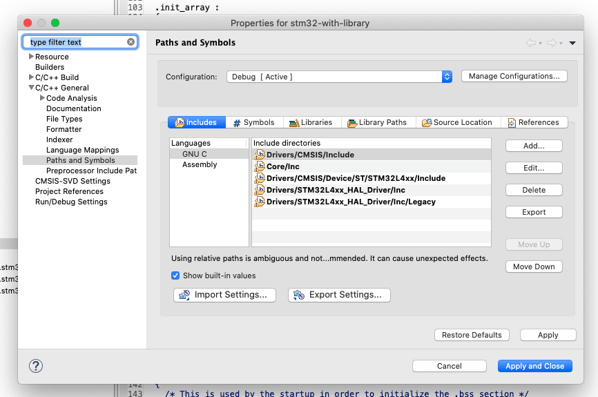
-
Click the Add... button under the Includes tab. Type
note-cinto the text box, click OK. Be sure to also press the Apply button.
-
Navigate to the Source Location tab, and click the Add Folder... button. Select the
note-cfolder from the list, and click OK. -
Finally, click the Apply and Close button.
Update User Code Blocks
- Now, open
main.cin theCore/Srcdirectory of your project. Look for the/* Private includes ---comment block at the top.
note/* USER CODE ... blocks are where you will want to place all of your code.
This ensures it will remain in place if you ever need to make changes in the
Device Configuration Tool and regenerate any of the auto-generated project
code.
- Add the following lines between the
/* USER CODE BEGIN Includes */and/* USER CODE END Includes */comments:
// C Includes
#include <stdbool.h>
#include <stddef.h>
#include <stdint.h>
#include <stdio.h>
#include <stdlib.h>
#include <string.h>

// 3rd-Party Includes
#include <note.h>- To make sure your Notecard knows which project it belongs to, you'll need to
specify the ProductUID. Using the ProductUID you specified when creating your
Notehub project, add the following definition to the private typedef section,
between the
/* USER CODE BEGIN PTD */and/* USER CODE END PTD */comments:
#define NOTE_I2C_BUFFER_SIZE 0xFF
#define NOTE_PRODUCT_UID "com.your-company.your-name:your_product"- Next, you'll need some static variables for I/O with the notecard. Add the
following to the private variable section, between the
/* USER CODE BEGIN PV */and/* USER CODE END PV */comments:
// Necessary for Notecard I/O functionality
bool i2c4Initialized = false;- And you'll also need to forward-declare a few functions needed for Notecard
communication. Add the following to the private function prototype section,
between the
/* USER CODE BEGIN PFP */and/* USER CODE END PFP */comments:
void MX_I2C4_DeInit(void);

// Note I2C Interface
bool noteI2CReset(uint16_t dev_addr);
const char * noteI2CTransmit(uint16_t dev_addr, uint8_t* pBuffer, uint16_t size);
const char * noteI2CReceive(uint16_t dev_addr, uint8_t* pBuffer, uint16_t size, uint32_t *available);

// Serial Debug
size_t noteDebugSerialOutput(const char *message);- Now let's add our main functionality for communicating with the Notecard.
Inside of the
mainfunction, look for the/* USER CODE BEGIN 2 */and/* USER CODE END 2 */comments and add the following code:
// Set Notecard System Interface
NoteSetFn(malloc, free, HAL_Delay, HAL_GetTick);

// Set Notecard I2C Interface
NoteSetFnI2C(NOTE_I2C_ADDR_DEFAULT, NOTE_I2C_BUFFER_SIZE, noteI2CReset, noteI2CTransmit, noteI2CReceive);

// Configure device with ProductUID
J *req = NoteNewRequest("hub.set");
JAddStringToObject(req, "product", NOTE_PRODUCT_UID);
JAddStringToObject(req, "mode", "continuous");
NoteRequest(req);
The call to NoteSetFn provides the note-c library with function pointers
for handling a few common operations. The NoteSetFnI2C function initializes
the I2C interface to the Notecard and passes in function pointers for
handling Notecard operations. You'll define all of these pointers shortly.
The last few lines use the "J" JSON library (bundled with the note-c
library) to create our first request to the Notecard. Then the request is
dispatched via the NoteRequest function.
-
Now it's time to supply the implementation of the user-defined functions (declared above).
MX_I2C4_DeInitis designed to reverse the effects of auto-generatedMX_I2C4_Initfunction. The primary purpose of this function is to demonstrate how to return the device to a clean state ready for hibernation.noteDebugSerialOutputis a wrapper aroundUSART2to make it easier to add logging messages to the code base.noteI2CReceiveis the I2C "read" function required by thenote-clibrary. It enables the STM32 Discovery to receive responses from the Notecard.noteI2CResetis a reset function required by thenote-clibrary. It allows the library to clean-up the STM32 Discovery I2C interface as needed.noteI2CTransmitis the I2C "write" function required by thenote-clibrary. It enables the STM32 Discovery to send requests to the Notecard.
Define the following functions, near the bottom, between
/* USER CODE BEGIN 4 */and/* USER CODE END 4 */:
// I2C4 De-initialization
void MX_I2C4_DeInit(void) {
  // Ensure idempotence
  if (!i2c4Initialized) { return; }
  i2c4Initialized = false;

  // Deconfigure Analogue filter
  HAL_I2CEx_ConfigAnalogFilter(&hi2c4, I2C_ANALOGFILTER_DISABLE);

  // Deinitialize
  HAL_I2C_DeInit(&hi2c4);
}

size_t noteDebugSerialOutput(const char *message) {
  static const size_t USART2_TIMEOUT = 250;
  size_t result = 0;

  HAL_StatusTypeDef status = HAL_UART_Transmit(&huart2, (uint8_t *)message, strlen(message), USART2_TIMEOUT);
  if (HAL_OK == status) {
    result = sizeof(message);
  } else {
    result = 0;
  }

  return result;
}

const char * noteI2CReceive(uint16_t dev_addr, uint8_t* pBuffer, uint16_t size, uint32_t *available) {
  const char *errstr;
  HAL_StatusTypeDef result;
  uint8_t query_request[2];
  query_request[0] = 0x00;
  query_request[1] = (size & NOTE_I2C_BUFFER_SIZE);

  uint8_t goodbyte = 0;
  uint8_t availbyte = 0;

  result = HAL_I2C_Master_Transmit(&hi2c4, (dev_addr << 1), query_request, sizeof(query_request), HAL_MAX_DELAY);
  switch(result) {
  case HAL_OK:
    errstr = NULL;
    break;
  case HAL_ERROR:
    errstr = ERRSTR("i2c: transmission error",i2cerr);
    break;
  case HAL_BUSY:
    errstr = ERRSTR("i2c: bus busy",i2cerr);
    break;
  case HAL_TIMEOUT:
    errstr = ERRSTR("i2c: transmission timeout",i2cerr);
    break;
  default:
    errstr = ERRSTR("i2c: unexpected transmission error",i2cerr);
    break;
  }

  // Only receive if we successfully began transmission
  if (!errstr) {
    uint8_t buffer[NOTE_I2C_BUFFER_SIZE];
    int readlen = (size + 2);
    result = HAL_I2C_Master_Receive(&hi2c4, (dev_addr << 1) | 0x01, buffer, readlen, HAL_MAX_DELAY);
    switch(result) {
    case HAL_OK:
      errstr = NULL;
      break;
    case HAL_ERROR:
      errstr = ERRSTR("i2c: read error",i2cerr);
      break;
    case HAL_BUSY:
      errstr = ERRSTR("i2c: bus busy",i2cerr);
      break;
    case HAL_TIMEOUT:
      errstr = ERRSTR("i2c: read timeout",i2cerr);
      break;
    default:
      errstr = ERRSTR("i2c: unexpected read error",i2cerr);
      break;
    }
    if (!errstr) {
      availbyte =buffer[0];
      goodbyte = buffer[1];
      if (goodbyte != size) {
        errstr = ERRSTR("i2c: incorrect amount of data",i2cerr);
      } else {
        memcpy(pBuffer, &buffer[2], buffer[1]);
      }
    }
  }

  if (errstr != NULL) {
    noteDebugSerialOutput(errstr);
    NoteDebugln(errstr);
    return errstr;
  }
  *available = availbyte;
  return NULL;
}

bool noteI2CReset(uint16_t dev_addr) {
  const char *errstr;
  uint8_t buffer[NOTE_I2C_BUFFER_SIZE];
  uint32_t available = 0;

  // Reset the I2C4 Interface
  MX_I2C4_DeInit();
  MX_I2C4_Init();

  // Empty the Notecard send buffer
  errstr = noteI2CReceive(dev_addr, NULL, 0, &available);
  while (!errstr && available) {
    errstr = noteI2CReceive(dev_addr, buffer, available, &available);
    if (errstr) { break; }
  }

  return !errstr;
}

const char * noteI2CTransmit(uint16_t dev_addr, uint8_t* pBuffer, uint16_t size) {
  const char * errstr;
  HAL_StatusTypeDef result;
  uint8_t send_buffer[256];
  send_buffer[0] = (size & NOTE_I2C_BUFFER_SIZE);

  memcpy(&send_buffer[1], pBuffer, send_buffer[0]);
  result = HAL_I2C_Master_Transmit(&hi2c4, (dev_addr << 1), send_buffer, (send_buffer[0] + 1), HAL_MAX_DELAY);
  switch(result) {
  case HAL_OK:
    errstr = NULL;
    break;
  case HAL_ERROR:
    errstr = ERRSTR("i2c: transmission error",i2cerr);
    break;
  case HAL_BUSY:
    errstr = ERRSTR("i2c: bus busy",i2cerr);
    break;
  case HAL_TIMEOUT:
    errstr = ERRSTR("i2c: transmission timeout",i2cerr);
    break;
  default:
    errstr = ERRSTR("i2c: unexpected transmission error",i2cerr);
    break;
  }

  return errstr;
}- In the
MX_I2C4_Initfunction, find the/* USER CODE BEGIN I2C4_Init 0 */and add the following right after:
// Ensure idempotence
if (i2c4Initialized) { return; }
i2c4Initialized = true;
Check your Work
Before moving on to sampling the BME680 and sending data to the Notecard, you
will want to confirm everything is working as expected. The easiest approach is
to set breakpoints on the return statements of the NoteRequest function, in
the n_request.c file, from the note-c library, and run your project in debug
mode.
- Select Run > Debug As > STM32 Cortex-M C/C++ Application from the menu bar.
noteIf this is your first time using your STM32 Discovery board, then you will likely be prompted to update the firmware of its built-in ST-LINK programmer. If you wish to upgrade, then click the Open in update mode button, followed by the Upgrade button on the ST-LINK Upgrade Screen.
- When the debugger launches, it will automatically break at the first line in
the
mainfunction, simply click the Resume button (F8). Now it should be halted at your breakpoint and you can confirm that thesuccessvariable is true.

If success is set to true, then your STM32 is talking to your Notecard! If
not, then please revisit and verify the previous steps. If you are still having
trouble, be sure to review the logs from the
serial debug output.
Add BME680_driver to your project
The easiest way to read from the BME680 sensor is to use the Bosch BME680 driver, so you'll start by downloading the driver and copying it to your project.
-
Clone or download
BME680_driverfrom its GitHub repo. -
Copy the complete contents of the library into your project by dragging it from the filesystem into the root of your project in the STM32CubeIDE. In the File and Folder Operation window, select the Copy files and folders option in the dialog and click OK.

-
Open the Project > Properties menu, expand the C/C++ General section, and select Paths and Symbols. Then, under the Includes tab, add the
BME680_driverdirectory just as you did thenote-cdirectory. Be sure to press the Apply button.
-
Also, remember to click on the Source Location tab, and add the
BME680_driverdirectory as a source folder.
-
To finish up, click the Apply and Close button.
Update User Code Blocks
- Open your
main.cfile and add the following include to the end of the/* USER CODE BEGIN Includes */section above<note.h>:
#include <bme680.h>- To keep from reading the sensor too fast, we need to specify a delay period
in the main loop (adjust as needed). Add the following definition in the
private typedef,
/* USER CODE BEGIN PTD */, section:
#define DELAY_PERIOD_MS (15*1000) // 15 seconds- Next, create an object to hold sensor readings, as well as a buffer for
displaying the result. Add the following in the private variable,
/* USER CODE BEGIN PV */, section:
// Data used during BME680 sampling
struct bme680_dev gas_sensor;
char i2c_reading_buf[100];
int8_t rslt = BME680_OK;- Then, create some forward declarations for the I2C read, write and delay
functions that the sensor will call. Add the following to the private function
prototype,
/* USER CODE BEGIN PFP */, section:
// BME680 Forward Declarations
int8_t bme680I2cRead(uint8_t dev_id, uint8_t reg_addr, uint8_t *reg_data, uint16_t len);
int8_t bme680I2cWrite(uint8_t dev_id, uint8_t reg_addr, uint8_t *reg_data, uint16_t len);- Now, in the
mainfunction, you'll want to configure the sensor. Add the following right after the/* USER CODE BEGIN 2 */comment:
// Configure the BME680 driver
gas_sensor.dev_id = BME680_I2C_ADDR_PRIMARY;
gas_sensor.intf = BME680_I2C_INTF;
gas_sensor.read = bme680I2cRead;
gas_sensor.write = bme680I2cWrite;
gas_sensor.delay_ms = HAL_Delay;
gas_sensor.amb_temp = 25;

// Initialize the driver
if (bme680_init(&gas_sensor) != BME680_OK) {
  char bme_msg[] = "BME680 Initialization Error\r\n";
  noteDebugSerialOutput(bme_msg);
} else {
  char bme_msg[] = "BME680 Initialized and Ready\r\n";
  noteDebugSerialOutput(bme_msg);
}

// Select desired oversampling rates
gas_sensor.tph_sett.os_hum = BME680_OS_2X;
gas_sensor.tph_sett.os_pres = BME680_OS_4X;
gas_sensor.tph_sett.os_temp = BME680_OS_8X;

// Set sensor to "always on"
gas_sensor.power_mode = BME680_FORCED_MODE;

// Set oversampling settings
uint8_t required_settings = (BME680_OST_SEL | BME680_OSP_SEL | BME680_OSH_SEL);
rslt = bme680_set_sensor_settings(required_settings, &gas_sensor);

// Set sensor mode
rslt = bme680_set_sensor_mode(&gas_sensor);

// Query minimum sampling period
uint16_t min_sampling_period;
bme680_get_profile_dur(&min_sampling_period, &gas_sensor);

// Sampling results variable
struct bme680_field_data data;- Before taking a reading from the sensor, you must implement the
bme680I2cReadandbme680I2cWritefunctions for theBME680_driverlibrary to call. Just after the/* USER CODE BEGIN 4 */comment, add the following:
int8_t bme680I2cRead(uint8_t dev_id, uint8_t reg_addr, uint8_t *reg_data, uint16_t len) {
int8_t result;
if (HAL_I2C_Master_Transmit(&hi2c4, (dev_id << 1), ®_addr, 1, HAL_MAX_DELAY) != HAL_OK) {
result = -1;
} else if (HAL_I2C_Master_Receive (&hi2c4, (dev_id << 1) | 0x01, reg_data, len, HAL_MAX_DELAY) != HAL_OK) {
result = -1;
} else {
result = 0;
}
return result;
}
int8_t bme680I2cWrite(uint8_t dev_id, uint8_t reg_addr, uint8_t *reg_data, uint16_t len) {
int8_t result;
int8_t *buf;
// Allocate and load I2C transmit buffer
buf = malloc(len + 1);
buf[0] = reg_addr;
memcpy(buf + 1, reg_data, len);
if (HAL_I2C_Master_Transmit(&hi2c4, (dev_id << 1), (uint8_t *) buf, len + 1, HAL_MAX_DELAY) != HAL_OK) {
result = -1;
} else {
result = 0;
}
free(buf);
return result;
}- Now you're ready take a reading. In the
/* USER CODE BEGIN WHILE */comment section, just after thewhile (1)statement, add the following code to get sensor data from the BME680 and output it to USB Serial:
// Allow BME680 to sample environment
HAL_Delay(min_sampling_period);

// Query the sample data
rslt = bme680_get_sensor_data(&data, &gas_sensor);

// Format results into a human readable string
sprintf(i2c_reading_buf,
  "T: %u.%u degC, H %u.%u %%rH\r\n",
  (unsigned int)data.temperature / 100,
  (unsigned int)data.temperature % 100,
  (unsigned int)data.humidity / 1000,
  (unsigned int)data.humidity % 1000);

// Publish result to connected PC
noteDebugSerialOutput(i2c_reading_buf);

// Wait between samples
HAL_Delay(DELAY_PERIOD_MS);

// Request the next sample
if (gas_sensor.power_mode == BME680_FORCED_MODE) {
  rslt = bme680_set_sensor_mode(&gas_sensor);
}Once you've added this, click the build icon in STM32CubeIDE to ensure your project compiles.
View Serial Output
-
To view the USB Serial output from your Nucleo board, you can use the console view of STM32CubeIDE. To do that, first click the debug icon in the STM32CubeIDE menu bar.

-
When the debugger connects, the default perspective will change and a console view will load at the bottom of the IDE. To add a USB Serial console, click the "Add console view" menu item and select "Command Shell Console."

-
Select Serial Port as the connection type and Click New… next to Connection Name.

-
Give the connection a name and select the Serial port that corresponds to the Nucleo board for your operating system. Set the baud rate to 115200, Data size to 8, parity to None and Stop bits to 1, then click Finish and OK.

-
When the Console connects, you'll see the name of your connection and the word "CONNECTED."

-
Click the play button in the debug UI to proceed running and you'll see sensor readings every 15 seconds.

Send Sensor Readings to the Notecard
Now that you're connected to the Notecard and successfully reading from the BME680, its time to bring the two sides together!
- Just after the
noteDebugSerialOutputline in thewhileblock, add the following code to create a new Note request to a file calledsensors.qoand add a body with the temperature and humidity readings from your sensor:
// Queue sensor reading to Notecard
J *req = NoteNewRequest("note.add");
if (req != NULL) {
  JAddStringToObject(req, "file", "sensors.qo");
  JAddBoolToObject(req, "sync", true);
  J *body = JCreateObject();
  if (body != NULL) {
    JAddNumberToObject(body, "temp", data.temperature / 100.0);
    JAddNumberToObject(body, "humidity", data.humidity / 1000.0);
    JAddItemToObject(req, "body", body);
  }
  NoteRequest(req);
}- Build your project and re-run it in debug mode to make sure that readings are still being captured. If you don't see any errors, your Notecard should be getting readings every 15 seconds, which you'll verify in the next section.
View Data in Notehub
Once you start capturing readings, your Notecard will initiate a connection to Notehub and will start transferring Notes. Depending on signal strength and coverage in your area, it may take a few minutes for your Notecard to connect to Notehub and transfer data.
-
Return to notehub.io and open your project. You should see your notecard in the Devices view.

-
Now, click on the Events left menu item. Once your sensor Notes start syncing, they'll show up here. You may need to refresh the page to see newly synced Notes.

Use Environment Variables
Environment variables are a Notehub state and settings management feature that allow you to set variables in key-value pairs, and intelligently synchronize those values across devices and fleets of devices.
You may wish to introduce environment variables into your application, for example to control how often to take sensor readings in your firmware. For more information, see our documentation on setting environment variables.
noteThis tutorial had you use several configuration settings that are best used when you have your Notecard connected to mains power.
-
In the
hub.setrequest, settingmodeto"continuous"tells the Notecard to maintain an active network connection. -
In the
hub.setrequest, settingsynctotruetells the Notecard to immediately synchronize inbound Notes and environment variables from Notehub. -
In the
note.addrequest, settingsynctotruetells the Notecard to immediately synchronize all outbound Notes to Notehub.
Because each of these settings cause the Notecard to use more power, you
may wish to disable them if you plan to transition your project to battery power.
You can run the command below to put your Notecard into periodic mode with
the sync argument turned off.
{
 "req": "hub.set",
 "mode": "periodic",
 "sync": false,
 "outbound": 60,
 "inbound": 120
}
Learn more about optimizing the Notecard for low-power scenarios in Low Power Design.
Next Steps
Congratulations! You've successfully connected your STM32 Discovery to your Notecard and built a basic IoT project.
If you're following the Cell+WiFi Quickstart, next we recommend learning how to send (and visualize) your data in a cloud application:
Use the Notecard to Send DataSet Up Your MicrocontrollerBuild Your First IoT App With Blues- Send Data to Your Cloud
At any time, if you find yourself stuck, please reach out on the community forum.