
Serial-Over-I2C Protocol
Unlike many fixed-length and register-based I2C protocols, the Notecard defines a variable-length, serial-over-I2C protocol that allows developers to handle JSON requests and responses in a similar manner as a direct Serial connection. The recommended way to use this protocol is with one of our firmware libraries in the Blues Inc. GitHub organization.
The Notecard operates the serial-over-I2C protocol at roughly 100kHz, in chunks of no more than 255 bytes, with a minimum 1ms delay between transactions.
 note
noteIn the following illustrations the host MCU acts as the I2C primary, and the
Notecard acts as the I2C secondary device. By default, the Notecard responds to
the 7-bit address (0x17), although this can be reconfigured in the Notecard
settings, using the card.io
command
using either the UART or USB interface.
What is I2C
IIC, I²C, and I2C, are synonymous and refer to the inter-integrated circuit bus. The I2C bus allows the different intergrated circuits of a hardware solution to communicate with each other using serialized messages, adhering to the I2C protocol. This guide assumes you have a basic understanding of the general I2C protocol, and will explain how the Blues Serial-over-I2C protocol is built on top of the standard I2C protocol. If you do not have a firm grasp of the I2C protocol, or wish to know more, you may reference the linked PDF guide from Texas Instruments.
Transaction Structure
The Blues Serial-Over-I2C Protocol uses the basic I2C transaction scheme, but uses a set of ordered transactions to describe and relay serial messages.
Ordered Transaction Listing*
- Handshake (data query) - Once, to validate configuration.
- Request (data write) - Repeatedly, until buffered request is sent.
- Poll (data query) - Poll every ~25ms, until Notecard responds.
- Response (data read) - Repeatedly, until buffered response is received.
- Go to step 2. Do not return to step 2 before completly reading the response in step 4.
*Transaction captured from the note-arduino library implementation of the Blues Serial-over-I2C protocol.
Handshake
See data query.
The "conversation" between I2C chips begins, with a handshake (or data query). This satisfies multiple requirements, as well as validates the hardware configuration.
First, the I2C write is addressed to a specific value (0x17 by default). If
the Notecard is configured with the correct address it will ACK, thus
validating the address. After the address, the host MCU will the send subsequent
byte parameters, which are immediately followed by a read request. Then the
Notecard responds, which indicates it received and understood the parameters,
and was also able to generate a response and send it on the bus. If the host
MCU understands this response, then the hardware is appropriately configured.
Furthermore, this provides the opportunity to the Notecard to indicate its
readiness based upon whether or not it has buffered bytes to send to the host
MCU (zero buffered bytes is expected).
Request
See data write.
The host MCU will craft a JSON request in a local buffer, then send it using
data write transactions. These transactions must be broken into chunks (not to
exceed 255 bytes), before they are sent across the wire. Once they have been
received by the Notecard they will be reconstructed until a newline \n is sent
to complete the request.
Poll
See data query.
While the Notecard is reconstructing and processing the JSON request, the host MCU will use a data query to poll the Notecard every ~25ms. Once the Notecard has completed processing the request and prepared a response, it will respond to the query letting the host know it has buffered bytes ready to send.
Response
See data read.
Finally, the host MCU will set aside a buffer to receive the Notecard's response, and request the transmission of the response. Now, the response is sent to the host MCU in chunks the size of the buffer or 253 (whichever is smaller).
These steps are meant to describe a typical request/response transaction between the host MCU and Notecard. It is by no means meant to be an exhaustive resource describing the transactions possible between the host MCU and Notecard. The goal is to provide a sufficient understanding of the communication between the chips, and give you a foundation to view, understand, and possibly create your own Serial-over-I2C transactions.
Data Query
In order to query the Notecard, the host MCU sends a zero length, no buffer, write transaction to the Notecard.
No Bytes Available

Here, you can see a write transaction to the address 0x17. Then a zero length
byte (0x00), indicating that the host is reading data from the Notecard. Then
another zero (0x00), which specifies the length of the buffer allocated to a
response string.
Immediately following the write transaction, the host sends a read transaction
to address 0x17. The Notecard responds with a zero (0x00), indicating it has
no bytes available to send. Then another zero (0x00), indicating no bytes were
sent in this response.
Bytes Available

Again, the host MCU sends a zero length, no buffer, write transaction to the
Notecard, followed by read transaction. However, in response to the read request, you see the Notecard respond
with a four (0x04), indicating it has four bytes available to send. Then
another zero (0x00), indicating no bytes were sent during this response.
Data Read
Response String: {}\r\n

The host MCU sends a write transaction to the address 0x17. Then a zero
(0x00), indicating it is attempting to read data from the Notecard.
Then a four (0x04), informing the Notecard it has allocated a four byte buffer
to hold the response string.
Immediately following the write transaction, the host sends a read transaction
to address 0x17. Then the Notecard responds with a zero (0x00), indicating
it has no more bytes available to send. Then a four (0x04), specifying the
length of the following response string. Subsequently, it sends the four bytes
of the response string (noted above). Finally, when the host MCU has filled it's
buffer, it NAKs the Notecard to inform it to stop sending data, and the
transaction is complete.
Data Write
Request String: {"req":"hub.log","text":"Hello, World!"}\n
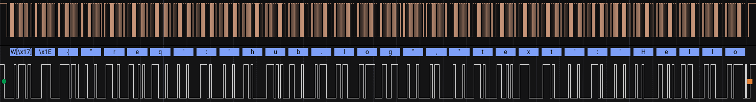

Here, the host MCU sends a write transaction to the address 0x17. Then an
integer value of 30 (0x1E), indicating it will attempt to write 30 bytes to
the Notecard. Then it proceeds to send the first 30 bytes of the request string.
Following the first write transaction, the host sends another write transaction
to address 0x17. Then an integer value of 11 (0x0B), which is the length of
the remaining characters of the request. Finally, after a short delay*, it sends
the last 11 bytes of the request string, which includes the newline
character (\n).
* A 20ms delay is commonly used to separate smaller I2C transactions known as "chunks", and a 250ms delay is required to separate "segments", ~256 byte I2C transactions. These delays ensure the Notecard has the ability to tend to other operations (i.e. managing the cellular connection).
noteIn the implementation used by this example, the internal buffer allocated to the
I2C bus is set at 32 bytes. Therefore, the write request must be broken into two
chunks (as shown above). Each chunk is, itself, a complete I2C transaction.
Ultimately, these chunks are reassembled by the Notecard, and processed once the
newline character (\n) has been encountered.
Transaction Walkthrough
Now that you have learned about the different parts of a transaction, let's take a look into how a typical transaction can be generated and the flow of the request and response pattern.
Below is the Arduino code used to create the oscilloscope captures shown and described above:
#include <Notecard.h>

Notecard notecard;

void setup() {
  notecard.begin();

  J *req = notecard.newRequest("hub.log");
  if (req != NULL) {
    if (!JAddStringToObject(req, "text", "Hello, World!")){
      // Failed to add log string!
    } else if (!notecard.sendRequest(req)) {
      // Failed to send request!
    }
  }
}

void loop() { }
First, focus on the notecard.begin(); statement. The call to begin()
configures the I2C peripheral, and sends an initial data query to
the Notecard. The initial query ensures the Notecard is available on the I2C
bus, responding, and ready to receive transactions.
After the call to begin, a log request is formed. The request is sent using
the notecard.sendRequest(req) statement. The call to sendRequest() generates
as many data write transactions as are required to send the
outbound request.
noteImportant: Before the host MCU may send a subsequent request to the Notecard, it must wait to receive the complete response for the previous request. It is unsafe to send a second request without waiting for the first to complete.
While waiting for the Notecard to process and respond to the request, the host MCU will issue a data query every ~25ms to poll the Notecard.
Once the request has been processed by the Notecard, then the Notecard will respond to the data query informing the host MCU there are response bytes available.
Finally, the host MCU allocates a buffer and extends a request to receive the response string by issuing as many data read transactions as necessary to receive the incoming response from the Notecard.