Using the Arduino IDE with Swan
Installation Prerequisites
Download and install STM32CubeCLT, which is a toolset that allows third-party IDEs to work with STM32-based host MCUs.
 note
noteAlternatively, you may install both STM32CubeIDE and STM32CubeProgrammer. These are much larger software packages that may not be necessary for your local development environment. Be sure to also follow these installation notes when installing STM32CubeProgrammer.
Linux only setup required for accessing the device in DFU mode and virtual COM port.
-
Create a
/etc/udev/rules.d/rule for the device in DFU mode.(echo '# DFU (Internal bootloader for STM32 MCUs)'; echo 'SUBSYSTEM=="usb", ATTRS{idVendor}=="0483", ATTRS{idProduct}=="df11", MODE="0664", GROUP="plugdev"') | sudo tee /etc/udev/rules.d/49-stdfu-permissions.rules > /dev/null -
Create a
/etc/udev/rules.d/rule for the device's virtual COM port.(echo '# Virtual COM Port for STM32 MCUs'; echo 'SUBSYSTEM=="usb", ATTRS{idVendor}=="0483", ATTRS{idProduct}=="5740", MODE="0664", GROUP="plugdev"') | sudo tee /etc/udev/rules.d/49-stvcp-permissions.rules > /dev/null -
Add active user to
plugdevgroup in/etc/group.sudo usermod -aG plugdev $USER
Using the Arduino CLI
As an alternative to using Arduino IDE to configure and build your project, you can use the Arduino CLI.
-
In order to specify Swan as the board, you need to first install the STM32duino core. You'll need a minimum of version
2.9.0of the STM32duino core installed.arduino-cli core install STMicroelectronics:stm32 -
You can then specify the Swan by using the board part number. For example:
arduino-cli compile --fqbn STMicroelectronics:stm32:Blues blinky.ino
Installing STM32duino in the Arduino IDE
-
Add the following URL to the Additional Boards URL in Settings/Preferences:
https://github.com/stm32duino/BoardManagerFiles/raw/main/package_stmicroelectronics_index.json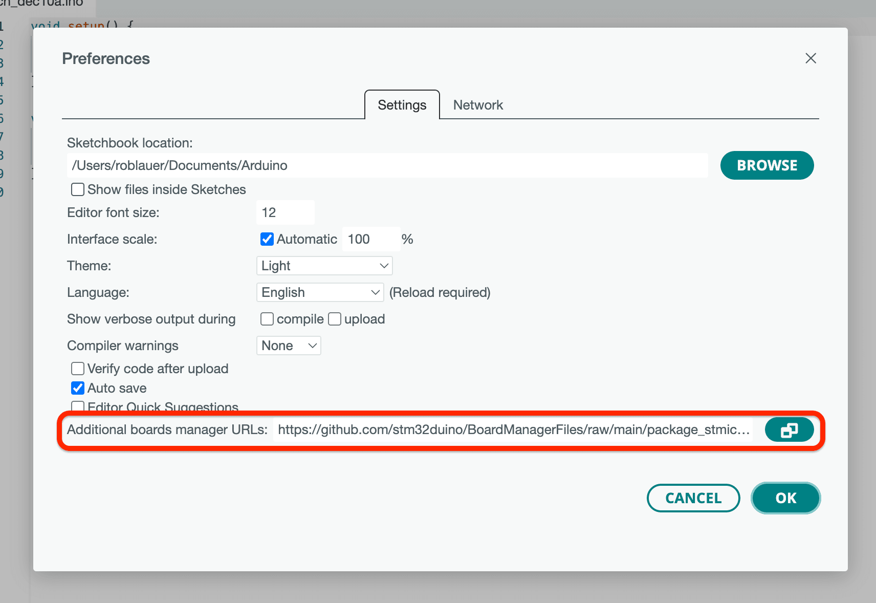
-
After restarting Arduino IDE, go to the Tools > Board > Boards Manager... menu option, search for "STM32 MCU based boards", and install or update to version
2.9.0or greater. -
Restart Arduino IDE.
Using STM32duino in the Arduino IDE
-
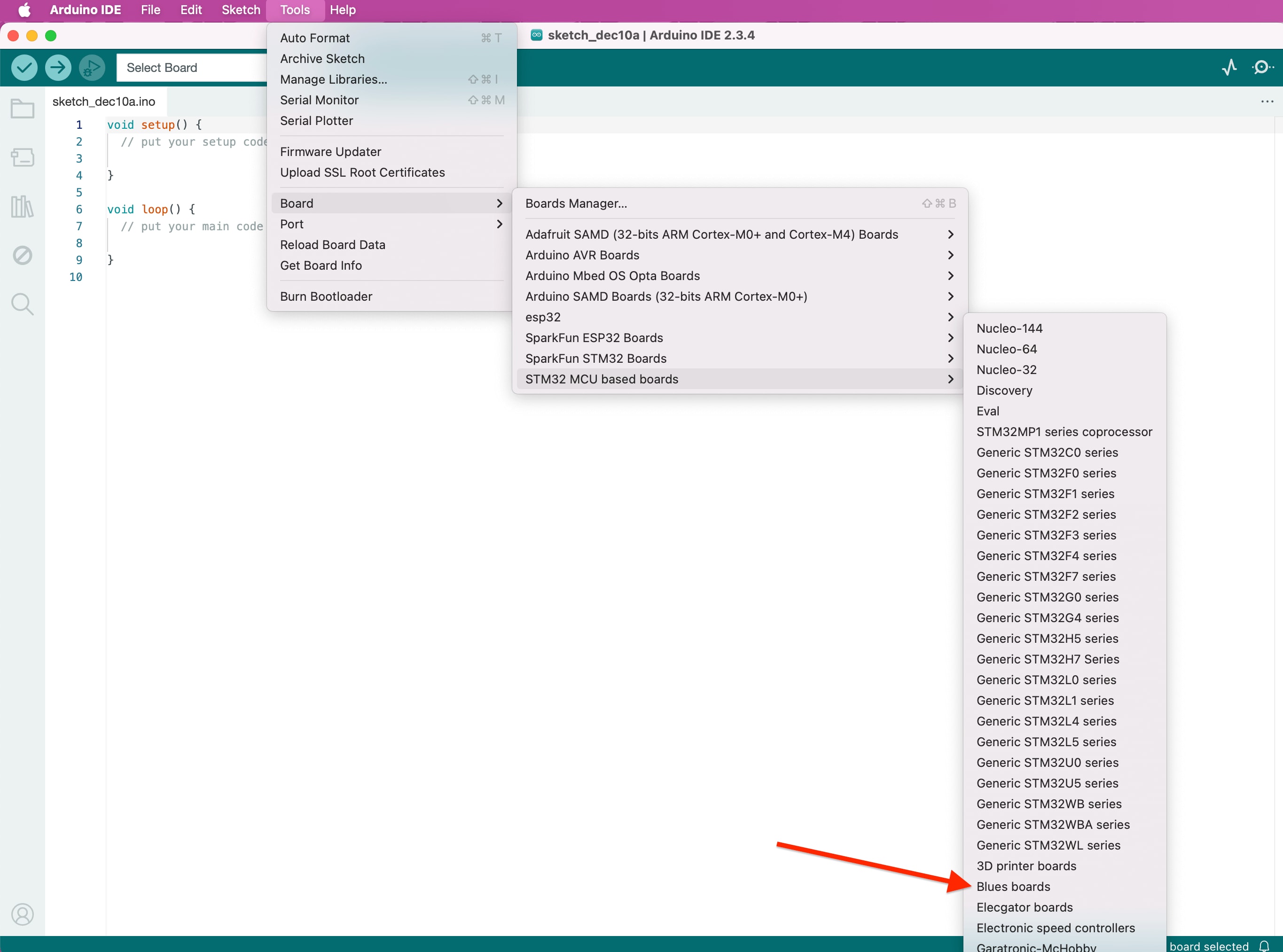
Under Tools > Board, select "STM32 MCU based boards", and then "Blues boards."
-
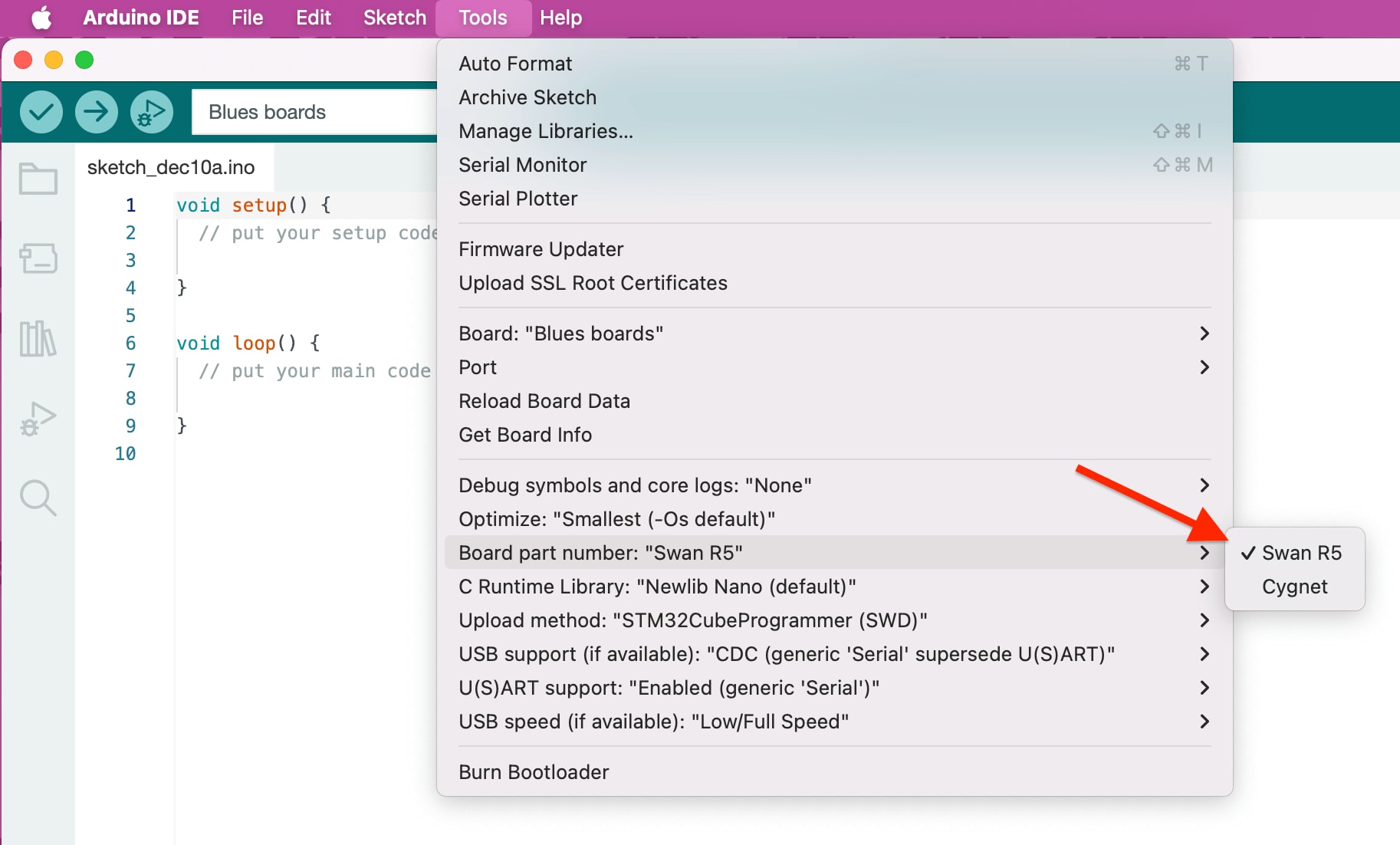
Next, under Tools > Board Part Number, select "Swan R5."
-
Lastly, under Tools > USB support (if available), select "CDC (generic 'Serial' supersede U(S)ART)."
Programming Swan with Arduino IDE
To program Swan in the Arduino IDE, you can use a programmer like the STLINK-V3MINI or program via a USB cable connected to your computer.
Programming Swan with the STLINK-V3MINI (Recommended)
-
Under Tools > Upload method, select "STM32CubeProgrammer (SWD)."
-
Plug the STLINK-V3MINI into your computer over USB.
-
Plug the Swan into a power source (e.g. a LiPo battery or your computer via USB).
NOTE: If you want to see Serial output from the Swan, you need to either use a USB cable as the power source or customize your sketch to use the STLINK-V3MINI for Serial output.
-
Plug the Cortex-Debug connector from the STLINK-V3MINI into the Swan.

-
Skip to the Blink the Onboard LED instructions below.
Programming Swan without the STLINK-V3MINI
-
Under Tools > Upload method, select "STM32CubeProgrammer (DFU)."
-
Connect the Swan's Micro USB port to your computer with a USB cable.

-
Press and hold the
BOOTbutton on the Swan, press and releaseRESET, then releaseBOOTto cause the Swan to jump into its bootloader. This sequence must be done every time you want to upload firmware to the Swan. -
Proceed to the Blink the Onboard LED instructions below.
Blink the Onboard LED
-
In the Arduino IDE, use File > New to create a new sketch.
-
Overwrite the provided boilerplate code with the following to cause the onboard LED to blink repeatedly:
// the setup function runs once when you press reset or power the board void setup() { // initialize digital pin LED_BUILTIN as an output. pinMode(LED_BUILTIN, OUTPUT); } // the loop function runs over and over again forever void loop() { digitalWrite(LED_BUILTIN, HIGH); // turn the LED on (HIGH is the voltage level) delay(1000); // wait for a second digitalWrite(LED_BUILTIN, LOW); // turn the LED off by making the voltage LOW delay(1000); // wait for a second } -
Upload this sketch to the Swan.
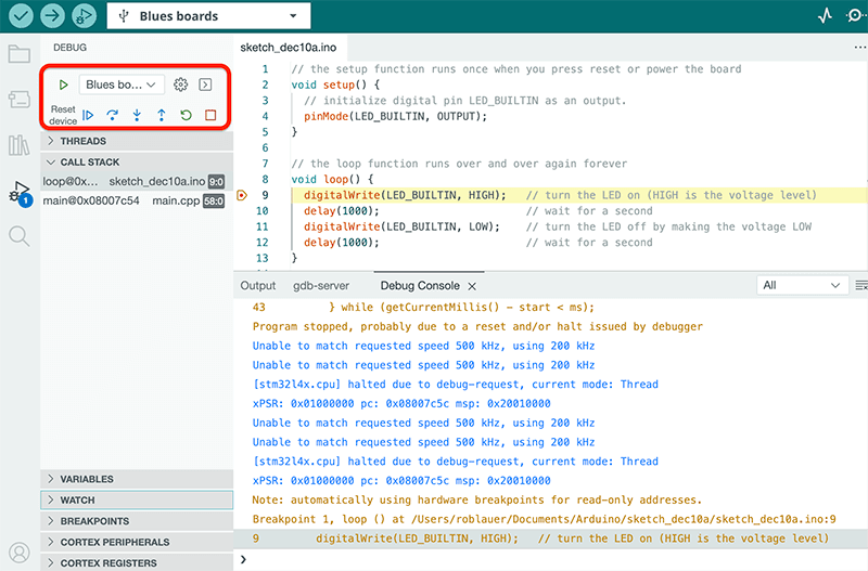
Step Debugging Swan with the Arduino IDE
Swan supports step debugging with Arduino Native Debugging on Arduino IDE when used with an attached STLINK programmer/debugger.
noteArduino Native Debugging requires usage of Arduino IDE v2.
-
Set one or more breakpoints on your sketch.

-
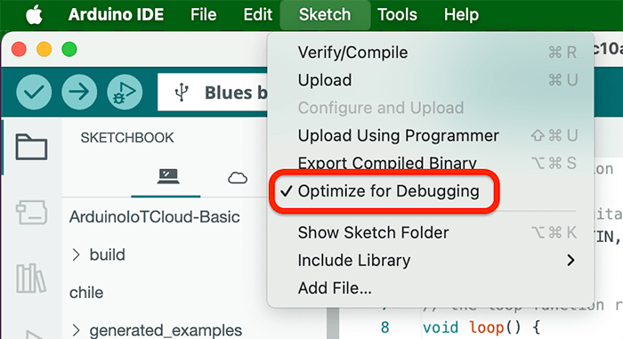
In the Sketch menu, select Optimize for Debugging.
-
Upload the sketch to Swan.
-
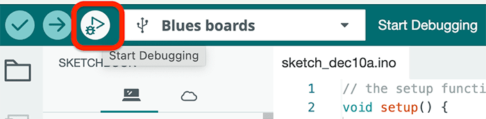
Click the Start Debugging button.
-
When a breakpoint is hit, use the Arduino IDE to step through relevant code blocks and inspect variables, view the call stack, and watch expressions.