
Attention Pin (ATTN) Guide
There are several situations where you may need your embedded application to be alerted the instant Notecard receives new information. This guide is designed to demonstrate how to leverage Notecard's attention interrupt.
At a high-level, your program will:
- Respond to a button click.
- Author a request to Notecard; instructing it to fire after a few seconds.
- Respond to interrupts and update an LED to visualize the behavior of the
ATTNinterrupt.
During the course of this example, you will learn:
- How to configure Notecard's attention interrupt.
- How to use the Blues Swan's onboard button and LED from your program.
- How to write and handle an interrupt service routine (ISR).
 note
noteAlthough this guide uses a Blues Swan microcontroller and a Notecarrier F to show how Notecard's attention pin works, you can use any combination of STM32 or ESP32 microcontroller and Notecarrier to complete this guide. Just note you may need to map the instructions to work with your specific hardware configuration.
Notecard Interrupt
Originally designed for low-power use cases, the Notecard attention interrupt is a latching interrupt. Meaning, once it fires, it stays in the fired position until it is manually reset.
The latching behavior enables you to leverage the interrupt in myriad ways:
- Notecard may idle or delay while waiting for communication from a cellular tower, while simultaneously disabling the host microcontroller with the enable pin.
- When used in a powered setting and connected to an interrupt capable pin on the host MCU, the host MCU can receive and respond to network communication as quickly as possible.
- The host MCU may optimize polling, by querying the logic value of the pin, as opposed to transacting with Notecard to look for new data.
To learn more about configuring the Notecard
ATTNinterrupts, read the Handling Notecard Interrupts section of the Notecard guide.
Hardware Setup
Ensure you have access to the following hardware:
- Blues Notecard
- Blues Swan STM32 host microcontroller
- Notecarrier F
- Male/male jumper wire
- Micro USB cable
- Momentary tactile push button (built-in to Blues Swan)
- LED (built-in to Blues Swan)
The Blues Starter Kit for Cell+WiFi includes a Notecard Cell+WiFi, Swan, and Notecarrier F.
Wiring
The attention, or ATTN, pin is exposed on the Notecarrier F, however it is not
wired to any pins that are exposed from the Feather socket. To utilize the
ATTN pin you must first decide how you would like it be used
(as described above), and then you must wire it the
corresponding pin.
You'll need to connect the N_ATTN pin of Notecard to an interrupt capable GPIO
pin on the Swan. Place the male/male jumper wire between the N_ATTN and F_D5
pins on the Notecarrier F.
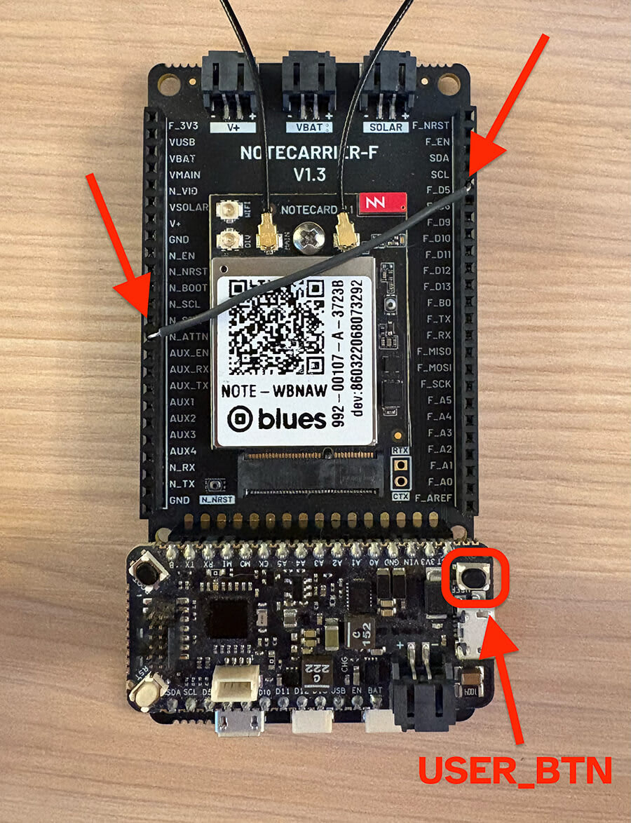
That's it! To complete the project, you will use the Swan's built-in LED,
LED_BUILTIN, and button, USER_BTN.
Firmware Breakdown
The following code sample demonstrates an Arduino implementation using the note-arduino SDK. However, you can implement the same workflow using any of the other Notecard SDKs.
The full Arduino sketch is available here on GitHub.
Definitions and Declarations
-
First things first, you'll need to include the Notecard library.
#include <Notecard.h> -
Next, you'll want to create a define for
IRAM_ATTRto add compatbility with STM32 hosts. On ESP32,IRAM_ATTRtells the function to use internal RAM.#ifndef IRAM_ATTR #define IRAM_ATTR #endif #define usbSerial Serial -
You will need to instantiate the Notecard class globally, which enables you to configure and interact with your Notecard device in both the
setupandloopfunctions.Notecard notecard; -
In order to optimize the interrupt execution, you need to declare a
volatile boolflag. This allows the interrupt and main loop to share state, which enables the interrupt to offload processing onto the main loop.volatile bool notecard_request_to_arm = false; -
Next, declare an interrupt to handle the button press event. This ISR will notify the main loop of the request by setting the flag to
true, after checking if theATTNpin is already armed.void IRAM_ATTR armInterrupt() { // Take no action when already armed if (digitalRead(D5)) { notecard_request_to_arm = true; usbSerial.println("INFO: ATTN interrupt armed!"); } } -
Declare an interrupt to handle the Notecard's
ATTNpin interrupt. Use the following code to set the Swan's built-in LED to follow the state of theATTNpin:void IRAM_ATTR attention() { // Visualize the attention pin state digitalWrite(LED_BUILTIN, digitalRead(D5)); }
setup Function
-
In
setup, you will start by enabling debug messages for the application.delay(1000); usbSerial.begin(115200); notecard.setDebugOutputStream(usbSerial); -
Next, you configure and initialize the Notecard.
// Initialize Notecard notecard.begin(); -
To register the
attentionISR to activity on pin5, you must use theattachInterruptAPI.// Attach Notecard Interrupt pinMode(D5, INPUT); attachInterrupt(digitalPinToInterrupt(D5), attention, RISING); -
To register the
armInterruptISR to a button press event on the Swan, you must use theattachInterruptAPI.// Attach Button Interrupt pinMode(USER_BTN, INPUT_PULLUP); attachInterrupt(digitalPinToInterrupt(USER_BTN), armInterrupt, RISING); -
Notecard can be powered seperately, and operates independently of the Swan. As a result, the Swan's built-in LED and the Notecard's
ATTNpin can get out of sync. To ensure alignment, you must initialize the state of the LED to match the state of theATTNpin.// Debug LED (mirrors `ATTN`) pinMode(LED_BUILTIN, OUTPUT); digitalWrite(LED_BUILTIN, digitalRead(D5));
loop Function
Due to the fact that most of the program's logic is executed through
event-driven code, the loop function is dedicated to servicing the button
press event.
-
When signalled by the interrupt driven flag,
notecard_request_to_arm, the MCU will construct a JSON request and send it to Notecard. If the message is sent successfully, then the Swan's built-in LED will be updated to reflect the state of the armed interrupt.void loop() { // Process arming request if (notecard_request_to_arm) { notecard_request_to_arm = false; // Arm ATTN Interrupt J *req = NoteNewRequest("card.attn"); if (req) { JAddStringToObject(req, "mode", "arm"); JAddNumberToObject(req, "seconds", 3); if (notecard.sendRequest(req)) { // Visualize the attention pin state digitalWrite(LED_BUILTIN, digitalRead(D5)); } else { usbSerial.println("ERROR: Failed to arm ATTN interrupt!"); } } } delay(20); }
Results
With your firmware uploaded to the Swan, when you press USER_BTN the
following should occur:
- Button Interrupt Triggered: The
USER_BTNpress triggers thearmInterrupt()function, which checks if theD5pin isHIGH. If it is, it sets the flagnotecard_request_to_arm. - Notecard Request Sent: In the main
loop, once the flag is set, acard.attnrequest is created withmode: "arm"andseconds: 3. When this request is sent, Notecard is instructed to "arm" its attention behavior for 3 seconds. - LED Mirrors D5's State: The LED is programmed to mirror the state of the
D5pin via theattention()interrupt service routine and the update in the loop. If Notecard, as a result of thecard.attncommand, pullsD5LOWfor 3 seconds, then the LED (which readsD5's state) will turn off for that duration.
Using the same techniques shown in this guide, you can use Notecard to interrupt your host when it receives environment variable updates, when it receives an inbound Note, when it detects motion, and more.
ESP32 Interrupt Handling
If you are using an ESP32-based host MCU, it's important to note that all GPIO pins on the ESP32 are interrupt capable. This is an amazing feature of the ESP32, and is not true of most microcontrollers. However, the ESP32's hardware interrupts require special handling, especially when using the Arduino board support package. Those details, and more, are discussed in this section.

An arbitrary momentary push button (B0) is denoted by the orange line
(bottom), and Notecard's ATTN interrupt is shown in white (top). As
illustrated by the yellow marker, the rising edge of the button is the trigger.
Once the button is released, the program generates and sends a request to arm
the attention interrupt (depicted by the red area). Lastly, the Notecard arms
the ATTN interrupt, observed as the white line being pulled LOW.
In the timing graph, you can see it takes ~80ms to service the request to arm. While 80ms may seem fast, it is quite slow for an MCU, and is precisely why the operation needs to be moved out of the interrupt and into the main loop.
noteESP32 Interrupt Service Routines should be decorated with IRAM_ATTR.
What is IRAM_ATTR?
By flagging a piece of code with the IRAM_ATTR attribute we are declaring that
the compiled code will be placed in the Internal RAM (IRAM) of the ESP32.
Otherwise the code is placed in flash storage and flash on the ESP32 is much
slower than internal RAM.
If the code we want to run is an interrupt service routine (ISR), we generally want to execute it as quickly as possible. If we had to "wait" for an ISR to load from flash, things would go horribly wrong.
 warning
Due to a
shortcoming
in Espressif System's esp32 Arduino Board Package, all interrupts must be
configured to fire on the same edge. To successfully observe the Notecard
attention pin interrupt, you must monitor the RISING edge. As a result,
any other interrupts in your project will also need to fire on the RISING
edge.