Blues Notecard® Datasheet: NOTE-ESP
Notecard Cellular
Notecard Cell+WiFi
Notecard for LoRa
Notecard for Skylo
Notecard WiFi
- NOTE-ESP
- NOTE-WIFI
An affordable, embeddable module for low-power WiFi connectivity.
Notecard WiFi is a version of the Blues Notecard dedicated for use on WiFi networks only. The device follows the same M.2 pinout as the cellular Notecards. What's more, Notecard WiFi uses the same powerful JSON-based programming interface, meaning that developers can easily add WiFi as a deployment option for their IoT solutions, with minimal impact to their existing host applications.
This product remains supported, but is no longer available for individual purchase through the Blues store. It is still available in minimum order quantities (MOQ). See Back Catalog Products for ordering details.
Functional Description
Notecard is an embeddable device-to-cloud data pump designed to remove the complexity and friction inherent in traditional IoT solutions. The Notecard family includes models supporting secure cellular, WiFi, LoRa, or satellite connectivity, enabling rapid development and iteration at a predictable, low cost. With as little as two lines of code on your host MCU, and no external libraries or dependencies, any Notecard model can securely move data from device to cloud.
Specifically, the Notecard NOTE-ESP is:
- A drop-in embeddable data storage and transport module for
WiFi IoT products, pumping JSON-formatted or binary data
("Notes") bi-directionally between device and cloud:
- JSON from/to MCU application using I2C, Serial, or USB.
- JSON to/from your cloud app using HTTPS or MQTT.
- JSON is auto-tagged with date/time.
- A removable and field-upgradable 30mm x 35mm system-on-a-module (SOM).
Features
- Low-power. Designed to operate on battery power, be "always-on", maintain time & location, while typically drawing less than ~12µA@5V when idle.
- MCU-agnostic. Will support any MCU or single-board computer as your app processor - even low-memory, 8-bit microcontrollers.
- Secure. Integrated STSAFE Secure Element with hardware crypto, true hardware random number generator, and a factory-installed ECC P-384 certificate provisioned at chip manufacture. Note that the certificate is no longer valid after November 16, 2047.
- Simple. Uses a JSON command interface over I2C, UART, or USB. Allows you to connect your 3.3V MCU.
- Power-conscious. Mostly-offline data sync mode for low power, and always-online mode for low latency.
- Efficient. Battery-powered WiFi without the complexity of managing connections, queues, or storage.
- Integrated. Utilizes an extremely thin cloud infrastructure that directly routes your data to where it belongs: AWS, Azure, GCP, or your own cloud.
- Built for data. Data routing and simple "no code/low code" visual data stream analysis through Notehub.io (SaaS), or host and integrate Notehub functionality into your own app (OSS).
Package Configuration
NOTE-ESP
- Product Name: Notecard WiFi v2
- Module: ESP32-S3-WROOM-1-N8R2
- Radio: 2.4 GHz 802.11b/g/n
Module Datasheet
Block Diagram
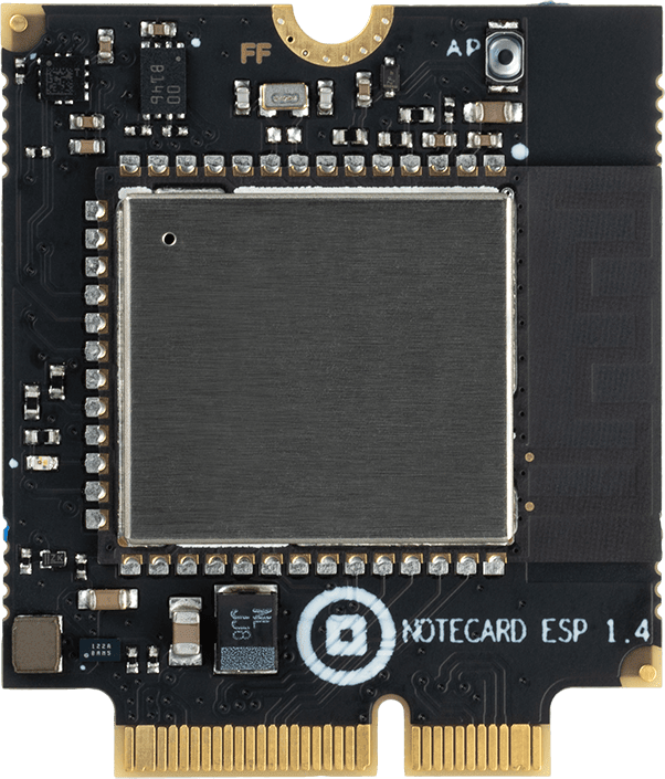
The Notecard WiFi is packaged using a compact removable form factor, 30mm x 35mm.
Open hardware schematics for both the Notecard and Notecarrier boards are available on GitHub, making it a straightforward task to embed the Notecard into a broad variety of host device designs.
The Notecard can interface with the host MCU at 3.3v levels.
| Front | Back |
|---|---|
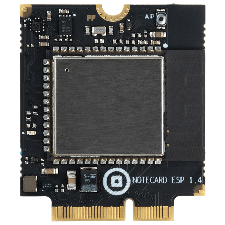 |  |
Typical Application
As shown below, Notecard is not an application processor and hosts no customer application code. It can be used as a data pump peripheral that is focused on bidirectional, asynchronous, secure data staging and transfer of JSON Notes.

Key Features
-
Security
Modern services require that the cloud and the device perform bidirectional authentication so that neither can be spoofed. For many applications it's important that over-the-air and over-the-wire data is encrypted. For this reason, the Notecard integrates an STSAFE Secure Element which contains symmetric keys manufactured into the chip. Neither the manufacturer of the Notecard nor the manufacturer of the customer's product has any need to handle or manage secure key material. The keys generated by STMicroelectronics for the Notecard use ECC with the NIST P-384 curve, and the signature algorithm is ECDSA-with-SHA384.
-
Low Power Consumption
The Notecard has sophisticated power control and makes heavy use of variable clock speeds. This enables the Notecard to have a typical idle current consumption of ~12µA@5V, while still supporting active UART and I2C communication.
Power Information
The Notecard's main supply voltage (VMODEM_P) is used for the WiFi radio
and associated circuitry. The Notecard has on-board regulators designed for
direct connection to a battery, so any voltage in the range of 2.5V to 5.5V may
be provided.
The Notecard WiFi typically sits in an ~12µA@5V idle mode waiting for a request
from the host MCU, however the Notecard current draw increases to about 80mA@5V
when the WiFi radio is active. The module also draws 10's of mA when the CPU is
performing session encryption. As such, it's recommended that VMODEM_P be
directly connected to a battery or other supply that is capable of
such brief spikes. It is also recommended that PCB traces for VMODEM_P and
GND be designed to handle such current.
The Notecard's logic voltage (VIO_P) is provided by the Notecarrier or host
system for digital communication; it will be 3.3V. Although the
Notecard typically draws very little current, this supply should be designed
with a 150mA budget allocated to the Notecard.
| Pin Name | Direction | Pin Numbers | Usage |
|---|---|---|---|
| GND | -- | 3,5,6,11,18,33,39,45,51,57,71,73 | Ground |
| VIO_P | IN | 2,4 | 3.3V @ 150mA |
| VUSB | IN | 13 | USB Serial proxy for "line power", with respect to dynamic line voltage detection |
| VMODEM_P | IN | 70,72,74 | 2.5V to 5.5V, capable of sustained 250mA draw |
In order to take advantage of various Notecard features pertaining to "dynamic
line voltage detection" (both now and in the future), or establish a USB Serial
connection to the Notecard, you must connect the VUSB power pin and support
the USB power design aspects of the Notecard.
Features include:
- Continuous mode behavior with the usb flag.
- Triangulate mode behavior with the usb flag.
- Monitor mode behavior.
Deep Sleep Mode on NOTE-ESP
Unlike other STM32-based Notecards, NOTE-ESP does not (by default) fall back to
a ~10uA current draw when it is idle. This is because the ESP32 doesn't have a
STOP mode equivalent where the UART and I2C can operate. The ESP32 does have a
deep sleep mode that draws ~10µA@5V, which can be configured by following this
guide on using
Deep Sleep Mode on Notecard WiFi v2.
Reset and Loss of Power
A power-loss event occurs whenever the Notecard loses power on VIO_P or
VMODEM_P, or the Notecard's NRST pin is pulled low. The modems used on all
Notecard variants are designed by their manufacturers to use best efforts to
maintain integrity when recovering from a power-loss event. That said, there is
a small chance that recovery will be impossible and the modem will be rendered
permanently unusable.
Upon recovering from any power-loss event, the Notecard initiates a procedure to ensure filesystem integrity. The Notecard also conducts a procedure upon first connection to Notehub after power loss to ensure consistency between Notecard's file system and Notehub's replica copy of those files. This verification procedure is done to protect and ensure the integrity of your product, and you should expect additional use of cellular bandwidth when these rare events occur.
It is the responsibility of every product designer to ensure that designs
utilizing Notecard provide constant power to VMODEM_P and VIO_P, at the cost
of as little as 8 µA, so as to ensure that power-loss events do not occur as a
matter of course from the perspective of the Notecard and its modem. If repeated
power failures are expected and unavoidable in a product's use, designs must
incorporate a small battery or lithium ion capacitor to provide backup power,
and the Notecard firmware should be configured to enter a quiescent state when
operating on its backup supply.
Frequent power-loss events will result in the voiding of the Notecard warranty. In addition, since repeated Notecard resets can be indistinguishable from "denial of service" attacks on the Notehub, Blues also reserves the right to deny access to devices that exhibit such behavior.
Antenna Requirements
The Notecard WiFi includes an embedded PCB antenna, though an external antenna can be used when connected through the u.FL connector on the Notecard. Any external antenna must support a 2.4 GHz frequency band.
The antenna included on the Notecarrier A series, as well as the external antenna provided with the Notecarrier Pi, support 2.4 GHz and have been tested with the Notecard.
Cellular Service
This section does not apply to the Notecard WiFi.
Pin Information
Pin Definitions
| Pin Name | Pin Description |
|---|---|
| ATTN_P | Attention pin (requires protection) |
| AUX_EN_P | Auxiliary serial port enable (requires protection) |
| AUX_RX_P | Auxiliary UART receive (requires protection) |
| AUX_TX_P | Auxiliary UART transmit (requires protection) |
| AUX1 | Auxiliary GPIO pin 1 |
| AUX2 | Auxiliary GPIO pin 2 |
| AUX3 | Auxiliary GPIO pin 3 |
| AUX4 | Auxiliary GPIO pin 4 |
| AUX_CHARGING | Charge detection |
| CTX | GPIO (outputs HIGH when ready to receive request) |
| GND | Ground |
| NC | No connection (reserved and must be left open) |
| NRST | Active-low (not) reset* |
| RTX | GPIO (used to wake ESP32) |
| RX_P | UART receive |
| SCL_P | I2C clock |
| SDA_P | I2C data |
| TX_P | UART transmit (requires protection) |
| USB_DN | USB data negative |
| USB_DP | USB data positive |
| VIO_P | I/O Voltage (requires protection)* |
| VMODEM_P | Voltage modem (requires protection)* |
| VUSB | USB Active indicator from 3V3 to 5V |
* See the power information section for important product design considerations related to reset and loss of power conditions.
Pin Description
Notecard M.2 Key E, Edge Connector Pinout
| Pin # | Pin Name | Func. Interface | Func. Interface | Pin Name | Pin # |
|---|---|---|---|---|---|
| 1 | NC | Power | VIO_P | 2 | |
| 3 | GND | Power | Power | VIO_P | 4 |
| 5 | GND | Power | Power | GND | 6 |
| 7 | USB_DP | USB Serial | SIM_VCC | 8 | |
| 9 | USB_DM | USB Serial | SIM_RST | 10 | |
| 11 | GND | Power | SIM_IO | 12 | |
| 13 | VUSB | USB Serial | SIM_CLK | 14 | |
| 15 | NC | SIM_NPRESENT | 16 | ||
| 17 | NC | Power | GND | 18 | |
| 19 | NC | VACT_GPS_OUT | 20 | ||
| 21 | NC | VACT_GPS_OUT | 22 | ||
| 23 | NC | NC | 24 | ||
| 25 | NC | NC | 26 | ||
| 27 | NC | NC | 28 | ||
| 29 | NC | NC | 30 | ||
| 31 | NC | AUX_DFU_BOOT | 32 | ||
| 33 | GND | Power | AUX_DFU_RESET | 34 | |
| 35 | NC | AUX_DFU_NACTIVE | 36 | ||
| 37 | NC | NCHG | 38 | ||
| 39 | GND | Power | I2C Serial | SCL_P | 40 |
| 41 | AUX_DFU_RX | I2C Serial | SDA_P | 42 | |
| 43 | AUX_DFU_TX | NC | 44 | ||
| 45 | GND | Power | Auxiliary Ports | AUX1 | 46 |
| 47 | RTX | Auxiliary Ports | AUX2 | 48 | |
| 49 | CTX | Auxiliary Ports | AUX3 | 50 | |
| 51 | GND | Power | Auxiliary Ports | AUX4 | 52 |
| 53 | NC | Attention | ATTN_P | 54 | |
| 55 | NC | Auxiliary Ports | AUX_EN_P | 56 | |
| 57 | GND | Power | Auxiliary Ports | AUX_RX_P | 58 |
| 59 | NC | Auxiliary Ports | AUX_TX_P | 60 | |
| 61 | NC | UART Serial | RX_P | 62 | |
| 63 | NC | UART Serial | TX_P | 64 | |
| 65 | BOOT | NC | 66 | ||
| 67 | NRST | Reset | NC | 68 | |
| 69 | NC | Power | VMODEM_P | 70 | |
| 71 | GND | Power | Power | VMODEM_P | 72 |
| 73 | GND | Power | Power | VMODEM_P | 74 |
| 75 | NC |
Link: Digi-Key part number of the connector - Both Digi-Key and Mouser have pictures for this part number that show a component with a different key, but both have links to datasheet/drawing/CAD models.
All pins whose Functional Interface is marked "Power" must be connected.
All pins named NC MUST have no connection and be left open because they are
reserved for future use. Furthermore, any pin not used in a design MUST also be
left open.
Those pins ending with _P may be optionally protected from anomalous external
conditions on some Notecarrier designs, depending upon use-case specific
requirements.
Technical Details
Host Microcontroller API
Notecard supports a rich, simple API whose syntax is standard JSON. The
developer can communicate requests to Notecard, generally by using little more
than printf functions available in most programming languages.
Serial Communication
JSON requests and responses (the Notecard's Application Programming Interface "API") may be sent over any of the following interfaces:
- USB Serial Interface
- UART Serial Interface
- I2C Interface
If NOT using a Notecard firmware library, you may unintentionally send requests to the Notecard so fast that you overflow the 1500 byte buffer used to receive data (whether it be I2C, Serial, or UART). The solution is to pause 250 ms after every 250 bytes sent and ensure the total size of each NDJSON object sent is no more than 8KB.
API Reference
For API usage, names, and parameters, please refer to the Notecard API Reference.
USB Serial Interface
The USB Serial Interface appears to the host as a USB 2.0 Full Speed CDC device. You can access it from Linux, Windows, or macOS without a device driver using terminal emulation software. Newline-delimited JSON requests may be sent directly as UTF-8 text over this port, or you may use the open-source Blues libraries for C, Python, Go, and Arduino.
| Pin Name | Direction | Pin Number | Usage |
|---|---|---|---|
| USB_DM | I/O | 9 | USB D- data signal |
| USB_DP | I/O | 7 | USB D+ data signal |
| VUSB | IN | 13 | +5V from USB |
| GND | I/O | 11 | Ground from USB |
UART Serial Interface
The UART Serial Interface operates at VIO_P at a fixed baud rate of 9600 using
eight data bits, no parity bit, and one stop bit. Newline-delimited JSON
requests may be sent directly as UTF-8 text over this port, or you may use the
open-source Blues libraries for C, Python, Go, and Arduino.
| Pin Name | Direction | Pin Number | Usage |
|---|---|---|---|
| RX_P | IN | 62 | Receive data signal |
| TX_P | OUT | 64 | Transmit data signal |
I2C Interface
The Notecard acts as an I2C secondary device operating at VIO_P, and it
implements a simple
Serial-over-I2C protocol.
You can access it from an embedded host using open-source Blues
libraries for C, Python, Go, and Arduino.
| Pin Name | Direction | Pin Number | Usage |
|---|---|---|---|
| SCL_P | IN | 40 | I2C clock |
| SDA_P | I/O | 42 | I2C data |
Older versions of Notecard WiFi (versions <= 3.2) do not have pull-up resistors on the I2C lines.
Host Microcontroller Hardware Interface
Attention Interrupt
Using software, you can optionally configure Notecard to use the ATTN output
pin to:
- Inform the host MCU of certain asynchronous events (such as incoming data availability, or Notecard motion) in an interrupt-driven manner rather than just polling.
- Place the host MCU into a power-off sleep state and wake it back up again.
| Pin Name | Direction | Pin Number | Usage |
|---|---|---|---|
| ATTN_P | OUT | 54 | Attention pin |
This pin operates at VIO_P. If it is unused it can be left disconnected.
Auxiliary Ports
An optional Auxiliary UART Serial Interface is available on the AUX_RX_P and
AUX_TX_P pins. This interface is inactive unless enabled by raising the
AUX_EN_P pin since this UART consumes extra power when in use. It operates at
VIO_P at a fixed baud rate of 115200 using eight data bits, no parity bit, and
one stop bit. If this interface is unused, the three pins can be left
disconnected.
The AUX1-4 pins operate at VIO_P and can be configured in software to operate
in several optional modes such as GPS Tracking Mode, GPIO Mode, and Internet
Button Mode. If these pins are unused, they can be left disconnected.
| Pin Name | Direction | Pin Number | Usage |
|---|---|---|---|
| AUX_EN_P | IN | 56 | Enables serial port on AUX_RX_P and AUX_TX_P |
| AUX_RX_P | IN | 58 | RX data for serial port enabled by AUX_EN_P |
| AUX_TX_P | OUT | 60 | TX data for serial port enabled by AUX_EN_P |
| AUX1 | I/O | 46 | General Purpose IO |
| AUX2 | I/O | 48 | General Purpose IO |
| AUX3 | I/O | 50 | General Purpose IO |
| AUX4 | I/O | 52 | General Purpose IO |
| AUX_CHARGING | I/O | 38 | Alt. attention pin or charge detection |
The auxiliary serial port is normally disabled because it consumes up to 100µA of power when enabled.
Outboard DFU Interface
As an alternative to using the Auxiliary Ports for Outboard DFU, there are also dedicated pins on certain Notecards. For more information on using this interface, check the detailed documentation
| Pin Name | Direction | Pin Number | Usage |
|---|---|---|---|
| ALT_DFU_BOOT | OUT | 32 | Used by Notecard to control the BOOT pin of the host MCU during Outboard DFU. Tri-state when Outboard DFU is not in progress. |
| ALT_DFU_RESET | OUT | 34 | Used by Notecard to control the RESET pin of the host MCU during Outboard DFU. Tri-state when Outboard DFU is not in progress. |
| ALT_DFU_ACTIVE | OUT | 36 | Driven low by Notecard to indicate to the host that an Outboard DFU is in progress. |
| ALT_DFU_RX | IN | 41 | Input on which Notecard receives data from the host during Outboard DFU. Tri-stated when Outboard DFU is not in progress. |
| ALT_DFU_TX | OUT | 43 | Output on which Notecard sends data to the host during Outboard DFU. Tri-stated when Outboard DFU is not in progress. |
Reset
Use of this pin is optional. If the host system has a global reset line, caution should be used when connecting this pin to the host system's reset because the Notecard may independently pull the line low in software. Restrictions on this pin are:
- If this pin is not used, it must remain not connected (
NC). - The pin is active-low. It must be held low for at least 350nS for a clean reset.
- This pin must never be pulled-up. A pull-up would interfere with the Notecard's own internal watchdog timer and thus will prevent reliable operations.
- Some Notecarriers may invert this signal to be active-high.
| Pin Name | Direction | Pin Number | Usage |
|---|---|---|---|
| NRST | I/O | 67 | Active-low reset |
Network Communication Behavior
The Notecard includes a built-in connection to Notehub.io
(specifically a.notefile.net:8086) and communicates over SSL. Outbound
connections speak directly with the Notehub session load balancer
(or "Discovery Service") for provisioning and device authentication. By default,
the TLS connection is unidirectional, but can operate bi-directionally,
if needed. The keys and certificates for each device are provisioned by
STMicrosystems inside the STSAFE secure element present on every Notecard.
Once the Discovery Service has provisioned or authenticated a device, it issues
a "ticket" and a Handler IP address that the Notecard can use to make subsequent
requests.
The Notecard can also connect to the Handler to do a constrained set of
remote procedure calls related to synchronization. If the Notecard determines
that the data queued for transmission to or from the Handler should be
encrypted, it opens a session to the Handler on port 8086. Otherwise,
an unencrypted socket is opened on port 8081.
The over-the-wire data transmitted on both sockets is highly byte-optimized, which is why raw SSL and TCP sockets are used, and not unoptimized HTTP/HTTPS transactions.
Specifications
General Characteristics
| Description | Value |
|---|---|
| Dimensions | 30mm x 35mm |
| Weight | 3 grams |
Electrical Characteristics
Absolute Maximum Ratings
| Description | Minimum | Maximum | Unit |
|---|---|---|---|
| Storage temperature | -40 | 90 | °C |
| Ambient operating temperature | -40 | 85 | °C |
DC Characteristics
| Description | Minimum | Maximum | Unit |
|---|---|---|---|
| Supply Voltage | 2.5 | 5.5 | V |
Ordering Information
Certifications
CE
CE certification indicates that a product complies with the essential requirements of relevant European health, safety, and environmental protection legislation. It is a mandatory conformity mark for products sold within the European Economic Area (EEA).
| Certification | Date |
|---|---|
| EN 300 328 V2.2.2 (2019-07) | September 2023 |
| EN 55032:2015/A11:2020 | September 2023 |
| EN 55035:2017/A11:2020 | September 2023 |
| ETSI EN 301 489-1 v2.2.3 (2019-11) | September 2023 |
| ETSI EN 301 489-17 v3.2.4 (2020-09) | September 2023 |
| IEC 62368-1:2018 | January 2024 |
| IEC 62368-1:2014 | January 2024 |
FCC
FCC certification indicates that a product complies with the regulations set forth by the Federal Communications Commission (FCC) in the United States. This certification ensures that electronic devices do not emit electromagnetic interference that could disrupt other electronic devices and communication systems.
| Certification | Date |
|---|---|
| 47 CFR FCC Part 15 Subpart B | September 2023 |
| 47 CFR Part 15, Subpart C, Section 15.247 | October 2023 |
ISED
ISED/ISEDC certification is issued by Innovation, Science and Economic Development Canada (ISEDC), formerly known as Industry Canada (IC). This certification ensures that electronic devices comply with Canadian regulations regarding radio frequency (RF) emissions and electromagnetic interference (EMI).
| Certification | Date |
|---|---|
| RSS-247 Issue 2 | October 2023 |
| ICES-003 Issue 7 | September 2023 |
Board Errata
- On units shipped where all large black capacitors indicate
JJ8, the idle current of the Notecard may measure slightly higher than the expected current draw indicated above.
Terms and Conditions
Visit Blues Hardware Terms & Conditions
Security and Vulnerability Scanning
As a part of our regular audit and scanning process, Blues Inc. performs full vulnerability scanning every six months. Any identified vulnerabilities will be analyzed, reported, and patched in a timely fashion, where appropriate.
Revision History
| Author | Date | Summary |
|---|---|---|
| Ray Ozzie | 2019-2020 | Document drafted |
| John Wiedey | 2020 | Various improvements |
| Sean Taylor | 2020 | Various improvements |
| Zachary J. Fields | 11 SEP 2020 | Updated information and translated to markdown |
| Brandon Satrom | 13 APR 2021 | Updated Country list based on carrier audit |
| Carlton Henderson | 12 JUL 2021 | Update coverage information |
| Carlton Henderson | 12 JUL 2021 | Fix block diagram photo |
| Brandon Satrom | 11 NOV 2021 | Added Certification Dates |
| Brandon Satrom | 07 JAN 2022 | Added RoHS Certification Dates |
| Brandon Satrom | 15 FEB 2022 | Add WiFi Notecard Datasheet |
| Rob Lauer | 25 AUG 2022 | Added updated certification data |
| Rob Lauer | 27 OCT 2022 | Update country coverage information |
| Rob Lauer | 13 JAN 2023 | Added RF performance information |
| Rob Lauer | 2 FEB 2023 | Warning re: STM32 light sensitivity |
| Kimball Johnson | 21 SEP 2023 | Updated for new Cell+WiFi, LoRa, and WiFi Notecards |
| Rob Lauer | 23 OCT 2023 | Update and clarify power consumption values |
| Rob Lauer | 31 JAN 2023 | Update Notecard for LoRa datasheet details |
| Rob Lauer | 16 APR 2024 | Updated for new Cellular (black PCB) Notecards, MB Cellular Notecards, and Notecard XP |
| Rob Lauer | 6 JUN 2024 | Added cell band support for Cellular Notecards |
| Rob Lauer | 23 JUL 2024 | Update pin definitions |
| TJ VanToll | 24 SEP 2024 | Adding Notecard for LoRa v2.1 information |
| Rob Lauer | 01 NOV 2024 | Adding Notecard for LoRa v2.1 castellated pin info |
| Rob Lauer | 06 NOV 2024 | Added errata for Notecard Cell+WiFi |
| Brandon Satrom | 06 DEC 2024 | Expanded reset and loss of power guidance |
| Rob Lauer | 20 DEC 2024 | Added PTCRB certifications for WBNAN, NBNAN, NBGLN |
| Rob Lauer | 5 MAR 2025 | Update AUX5 to AUX_CHARGING |
| Rob Lauer | 22 MAY 2025 | Fix labelling of NC pins |
| Rob Lauer | 13 JUN 2025 | Update certifications |
| Rob Lauer | 21 JUL 2025 | Update certifications for WBNAN, NBNAN, NBGLN |
| Rob Lauer | 28 JUL 2025 | Update certifications for all Notecard SKUs |
| Rob Lauer | 17 NOV 2025 | Add FCC and IC IDs for all Notecard Cellular SKUs |
| TJ VanToll | 21 JAN 2026 | Added Notecard for Skylo |
Contact Information
Blues Inc.
https://blues.com
50 Dunham Ridge Suite 1650
Beverly, MA 01915
support@blues.com