Low-Power Hardware Design Application Note
Table of Contents
- Introduction
- General Design Guidelines
- Host MCU Recommendations
- Power Supply Selection
- Component Recommendations
- Measuring Power Consumption
- Notecard Electrical Characteristics
- Design Review Accelerator
- Ordering Information
- Terms & Conditions
- Contact Information
- Revision History
Introduction
This application note covers how to design a low-power system that uses the Notecard for wireless communication. The Notecard is a family of system-on-module devices that can be used to add drop-in wireless connectivity for products.
Whether you are designing a product from scratch or adding the Notecard to an existing product to supply wireless connectivity, this document will help you navigate the design process and help you overcome some of the common challenges of designing a low power integration.

Notecard is designed to always be powered. Moreover, Notecard power architecture is designed so that it will gracefully enter and leave sleep states on its own or by software triggers (see Notecard API card.aux). This has the advantage of reducing wear on the components from power cycling as well as keeping the modem ready at all times.
General Design Guidelines
This application note focuses on low power; however, if you are new to Notecard, we strongly recommend you start with the Carrier Design Guide for an overview of our recommendations.
As detailed in that guide, Notecard-based products should be designed with an M.2 Key E connector such as Amphenol MDT420E01001 and secured to a grounded standoff with mounting screw. Blues reference designs use a Würth Elektronik 9774025151R paired with an M2.5x4 metric machine screw.
In future Notecard designs, the M.2 mounting screw and standoff will stay in the same location; however, the Notecard's length may be extended by up to 7mm (from today's 35mm to 42mm) — to account for enhanced or additional components including, in some configurations, an RF antenna.
The hardware design files for every Notecarrier that Blues produces are open source and available in our GitHub hardware repository.
Notecarrier schematics contain our best practices around Notecard-based design, and we encourage you to consult these when integrating and building new products and are referenced throughout this document.
Notecard Modes of Operation
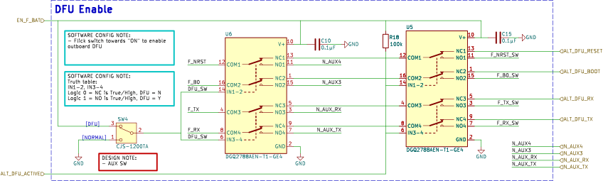
The Notecard can be configured to operate in five different modes: periodic, continuous, minimum, off, and DFU. These modes refer to the frequency of the cellular modem's activity. Periodic mode can be configured in software to communicate with Notehub at set intervals. This is ideal for low-power operation because every modem transmission expends joules.
Continuous mode like the name implies is a mode where the Notecard cellular modem does not stop transmitting. This mode is appropriate for certain customer applications.
To minimize power device power consumption, it’s important to understand the different modes of operation and how to set them with the Notecard API hub.setrequest.
For a deeper discussion of the low-power software features available to Notecard, please see the Low-Power Firmware Design Guide
Notecard can do dynamic line voltage detection or establish a USB Serial connection to Notecard, you must connect the VUSB power pin and support the USB power design of Notecard.
For more see the Carrier Design Guide.
Host MCU Recommendations
The host microcontroller you select will affect your overall power consumption dramatically. While you can use almost any host microcontroller with Notecard, we have had good experience with the following MCUs for low power designs.
Regardless of which MCU you select, the overall integration with the Notecard will be relatively similar.
ST STM32
The STM32 from ST is a family of 32-bit microcontrollers based on the Arm Cortex-M with low power consumption and solid performance. The STM32L Series of MCUs pair nicely with low-power design due to the following key features:
- Ultra-low-power mode (ULPM): 8nA with backup registers without real-time clock (5 wakeup pins)
- ULPM + RTC: 200nA with backup registers (5 wakeup pins)
- ULPM + 8 Kbytes of RAM: 195nA
- ULPM + 8 Kb RAM + RTC: 340nA
For more technical information, see the STM32 microcontroller system memory boot mode application note.
Ensure you have access to the Notecard's debug port and various auxiliary ports: AUX1, AUX2, AUX3, AUX4, AUX_CHARGING, ATTN_P, AUX_EN, AUX_RX, AUX_TX, RX_P, TX_P even if you don't intend to use these pins as they will aid in the certification process in addition to offering additional debugging features and flexibility. No matter what host MCU you decide to design in, we have tools and resources to help you with your design. Check out our Design Review Accelerator for more on how we can help you and your team.
Espressif ESP32
The ESP32 from Espressif is another 32-bit MCU with a low-power sleep state which consumes less than 5μA. It also features onboard WiFi and Bluetooth/Bluetooth LE, which may be appealing for certain product use-cases.
See the Espressif ESP32 Design Guide for their recommendations on working with the MCU.
Keep in mind that Notecard can be configured to power off or down the host MCU when not in use, the power consumption of the host MCU is not as hypercritical as the rest of the design.
Reference Design Example
This schematic shows a barebones design for integrating Notecard with your MCU of choice. It is important to note how Notecard interfaces with the host MCU and the power tree that must be provided for proper functionality.
A barebones low-power reference design for integrating Notecard with an external MCU.
Above is an interactive KiCanvas-powered schematic showing how to integrate Notecard with an external MCU.
-
You can zoom in and out using your mouse wheel or, if on a laptop, hold CTRL while dragging two-fingers on your trackpad.
-
For more precise zooming, click on a component to highlight it and then click the "Zoom to Selection" button on the bottom right of canvas to get a closer look.
-
To download the schematic click the "Download" button in the upper right corner.
KiCanvas is an interactive, browser-based viewer for KiCAD schematics and board files created by Thea "Stargirl" Flowers.
These pins (AUX3, AUX4, AUX_RX AND AUX_TX) are required in order to perform OTA updates to your choice MCU via Notecard from Notehub- without them, you must have physical access to your device in order to update the MCU's FW.
We also recommend wiring the Notecard ATTN pin to a wake-capable GPIO on the
host MCU. ATTN is how the Notecard signals the host to wake on events like
motion, inbound data, USB insertion, or environment variable changes. Without
it, the host has no efficient way to sleep between events. See the
Low-Power Firmware Design Guide
for the corresponding card.attn configuration.
In the schematic above, the power source is shown as a Scoop, which is an ideal way to provide power back-up to your product, but could just as easily be a Li-Po battery or line power that meets Notecard power supply requirements — the decision of which power source to use is very much use-case specific.
Power Supply Selection
We recommend selecting and designing your power supply conservatively to accommodate all possible Notecard SKUs. For some designs, consider our Scoop as a better alternative to LiPo battery for your design.
Notecard's main supply voltage (VMODEM_P) is used for the cellular modem and associated circuitry. The Notecard has on-board regulators designed for direct connection to a battery so any voltage in the range of 2.5V to 5.5V may be provided.
Notecard's logic voltage (VIO_P) is provided by the Notecarrier or host system for digital communication; it will be either 1.8V or 3.3V. Although the Notecard typically draws very little current, this supply should be designed with a 150mA budget allocated to the notecard. Utilizing a 1V8 MCU (and potential peripherals) will give you the best effiency and no level shifting is required. If you hope to interface a 3.3V or 5V MCU (for example) with Notecard, or if you're hoping to interface peripherals at various logic voltages (for example) with Notecard, level shifting is required.
Cellular Notecards have specific power requirements to satisfy the power demands of the cellular radio. Your design must supply: 2V5 to 5V5 and be capable of a sustained 750mA draw and brief 2A bursts. This voltage must be applied to the VMODEM_P pins of the M.2 connector (pins 70, 72, and 74).
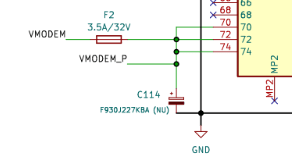
Your power design must support for bursts of 2A to meet the requirements for GPRS/GSM communication. This is critical and must not be overlooked.
To power the Notecard MCU and its peripherals, you can supply a voltage of 1V8 or 3V3, capable of at least 150mA draw. We recommend designing for 500mA draw to allow for more headroom. This voltage must be applied to the VIO_P pins of the M.2 connector (pins 2 and 4).
| Description | Minimum | Maximum |
|---|---|---|
| Supply Voltage (V) | 2V5 | 5V5 |
| Supply Current (mA) | 500mA | 2A |
Keep in mind that a powered Notecard at idle consumes ~8µA@5V.
Minimizing Phantom Current
The "phantom current" of your device is whatever the board draws when the host MCU is sleeping and no work is in progress. It is the single biggest determinant of battery life for a mostly-idle product. Here are three suggestions to keep it low:
-
One always-on 3V3 rail, chosen for ultra-low quiescent current. This rail powers Notecard
VIOand any MCU circuitry that must survive host sleep. Prefer non-switching regulators with sub-µA Iq — for example the Richtek RT6160A draws ~1µA@3A. Every other rail in the design should be switched on and off via anENinput driven by a host GPIO, so only the one always-on rail contributes to idle draw. -
Leave
VIOpowered at all times and do not reset the Notecard after boot. Notecard is designed to be continuously powered, and power-cycling it is counterproductive asVIOidle draw is already under 10µA. -
Be deliberate with pull-up, pull-down, and voltage-divider resistor values. A 10kΩ pull-up on a 3V3 rail burns 330µA whenever the pin is low, which is far more than Notecard itself. For pins that spend most of their time in one state, size resistors in the 100kΩ–1MΩ range, or use a MOSFET to gate the divider only when you need to sample it.
Component Recommendations
Level Shifting
Depending on your connecting MCU and various peripherals, you may require level shifting the logic between devices; Notecard logic requires 1V8 OR 3V3. e.g. If your design has peripherals, they may not be supported by the Notecard without level shifting to 1.8V or 3.3V.
While VMODEM (pins 70, 72, 74) operates at 2V5 ~ 5V5 whereas VIO (pins 2 and 4) typically operates at either 1V8 or 3V3.
The Note-Wifi only takes 3v3 for VIO so if you want to make a product that works on cell and WiFi you need to supply 3v3 or at least the provision for switching to 3v3 if you want to run cellular at 1v8 and be able to use Note-Wifi when necessary..
Because the operating voltages may differ, a logic shifter must be implemented; this doubles as protection between your Notecard and external peripherals — which is strongly suggested.
PMGD175XNE is a dual N-channel MOSFET used on the Notecard in conjunction with on-Notecard i2c devices for level shifting and isolation purposes.
The i2c Serial interface uses the SCL_P (pin 40) and SDA_P (pin 42) signals.
Notecard provides 10KΩ pull-ups on SCL_P and SDA_P — no additional pull-ups are necessary.
You should provide appropriate termination resistance on SCL_P and SDA_P. The Notecarrier reference designs use two 100Ω resistors for this purpose. For more information, please consult the Notecard Carrier Board Design Guide.
Level shifters double as digital isolators. The OE (output-enable) pin on
parts like the
TXS0102DCUR
lets the host drop a bus to high-impedance during sleep. This is the cleanest
way to handle peripherals that can't otherwise be disabled — external UARTs,
fixed-drive outputs, or any IO that would otherwise drag down a Notecard rail
during host sleep. Tie OE to a host GPIO and deassert it when entering
low-power mode.
Level Shifting 1V8
For 1V8 we recommend the MAX17225 boost converter paired with a logic shifter such as the TXS0102DCUR or the NVT2002TLH. These parts have a low shut down current, high efficiency, and small quiescent current giving a broad feature set. The MAX17225 has a leakage current of only 0.1nA which is far superior to most others in the µA range.
MAX1722X
We selected the MAX1722X because its job is to power the Notecard MCU, accelerometer and temp sensor, and the crypto engine. It has a very small quiescent current and has 95% peak efficiency. It also meets the 150mA spec in the block diagram above, plus a bit of overhead.
 MAX17225 block diagram from the MAX17225 datasheet
MAX17225 Features:
- 300nA Quiescent Supply Current Into OUT
- True Shutdown Mode
- 0.5nA Shutdown Current
- Output Disconnects from Input
- No Reverse Current with VOUT 0V to 5V
- 95% Peak Efficiency
- 400mV to 5.5V Input Range
- 0V88 Minimum Startup Voltage
- 1V8 to 5V Output Voltage Range
- 100mV/Step
- Single 1% Resistor Selectable Output
- 1A output
Three specs to keep in mind while selecting a 1V8 level shifter are efficiency, shutdown current, and quiescent current. It is also important to keep protection and any kind of leakage current in mind when selecting your level shifter.
ADP1606A
When selecting a power supply for your low-power design, it is critical to select a DC/DC with low quiescent current and high peak efficiency. The MAX1722X and ADP1606ACPZN1.8 appear like similar parts, and one may be cheaper, available, and easier to source than the other, but for the use-case of low-power design, the MAX1722X would be a better option.
 ADP1606 schematic diagram from the component datasheet.
ADP1606 Features:
- 23uA quiescent current
- True Shutdown Mode & Power Isolation
- 96% Peak Efficiency
- Fixed 1V8 output
- 1A output
The reason is because the MAX1722X mates perfectly with the power profile within Notecard that was specifically designed to cater to the health of cellular modem. In addition to that, our aim is for sub 1µA draw in shut down modes so the MAX1722X is eating up 0.3µA of that 1µA goal/budget whereas the seemingly similar part (ADP1606A) would take 23µA of that 1µA goal/budget.
Level Shifting 3V3
Now that you are familiar with some of the low-power considerations in selecting components for level-shifting, the schematic from Notecarrier F's 3V3 level-shifting is provide for guidance.
 Notecarrier F 3V3 logic level shifter schematic.
Boost Converter
To satisfy the Notecard's wireless modem power demands — especially at sudden intervals — a boost converter is used. The boost converter takes anything below the input voltage threshold and boost it so that it is within specification.
The specific power requirements for the modem will change based on the activity of the modem as well as if it is in a low-power sleep state. It is strongly suggested that you use one of the following boost converters for optimal low-power performance.
The table below is a list of similar DC/DC boost converters with fixed 1V8 output option and their listed iq for comparison.
| DC/DC Component | Typical iq | Description | Shutdown Current |
|---|---|---|---|
| MCP1640 | 0.7µA | 0V8 to 5V5; 350mA | 0.3µA |
| LTC3525 | 3µA | 0V5 to 3V3; 400mA | 0.5µA |
| TPS61236 | 5µA | 0V5 to 1V8; 3A | 0.01µA |
| TPS61220 | 5µA | 0V7 to 5V5; 200mA | 0.2µA |
| TPS61030 | 10µA | 1V8 ~ 5V5 to 1V8; 3.6A | 0.01µA |
| ADP1612 | 900µA | 1V8 ~ 5V5 to 1V8; 1.4A | 0.01µA |
It's helpful to use a table such as this when comparing efficiency and other specifications to meet your design requirements.
Power supply manufacturers will often-times have a product comparison matrix showing each of their part numbers and where they fit on a list such iq, maximum output current, maximum fixed output voltage, etc.
TPS61021A
 TPS61021A schematic from the Texas Instruments datasheet.
Below is a list of similar DC/DC boost converters with fixed 3V3 output option and their listed iq for comparison.
| Potential DC/DC Component | Typical iq | Description | Shutdown Current |
|---|---|---|---|
| TPS61021A | 17µA | 0V5 ~ 4V4 to 1V8; 3A | 0.5µA |
| TPS61236 | 5µA | 2V3 ~ 4V5 to 5V; 6.5A | 0.01µA |
| MCP1640 | 19µA (PFM) | 2V0 ~ 5V5 to 5V; 300mA | 0.7µA (PFM) |
| TPS61220 | 5.5µA | 0V7 ~ 5V5 to 1V8; 200mA | 0.2µA |
This is a good starting point in comparing efficiency, availability, cost, and other specifications to ensure it will meet your design requirements.
Buck boost
The TPS6302x is a buck boost that caters to the unique requirements of the Notecard modem and the USB spec. The schematic from the Notecarrier F shows how to implement the TPS6302x in your design.
 Notecarrier F schematic where the TPS6302x buck boost converter is used.
Measuring Power Consumption
Idle draw is the number you optimize against. Component datasheets give you the lower bound, but the only way to know what your assembled board actually pulls is to measure it.
Bench measurement with a Joulescope
For the most accurate idle-energy measurement during bring-up, use a Joulescope in place of the battery. Power the Joulescope itself from a 3V8 bench supply (to approximate a healthy Li-Po) and wire it in-line where the battery would connect. The Joulescope can log current over wide dynamic ranges (nA to A) without range-switching artifacts, so it will catch both the sub-10µA idle floor and the 2A modem bursts.
In-field measurement with Blues Mojo
If the device is already deployed, or you need to correlate power draw with real workloads, design-in a Blues Mojo from the start. Mojo is a small current-measurement module that sits in the power path of Notecard (or the entire board) and lets the host sample power consumption at key moments. This is especially useful for validating voltage-variable behaviors under realistic battery curves.
The Power Usage Estimates section of the Low-Power Firmware Design Guide contains measured reference values (taken with a Mojo under standardized conditions) that you can use as sanity checks against your own measurements.
Notecard Electrical Characteristics
Both "absolute maximum ratings" and "DC characteristics" may be found in each Notecard's datasheet.
Design Review Accelerator
The Blues Design Review Accelerator is a complementary service offered to customers building Notecard and Notehub-based solutions. Customers can take advantage of this service to reduce implementation costs, product spins, and overall time-to-market.
As part of the service, customers will collaborate with blues technical support and applications engineers to define their product architecture, select key components, and ensure that their application is designed to utilize the best of what the Notecard and Notehub have to offer.
The service includes:
- Product architecture consulting
- A Product ideation session with blues product experts
- Schematic review
- PCB layout review
- Component placement consulting
- Component selection guidance for BOM cost optimization For additional information about this service and to schedule an introductory conversation, please contact the Blues Team.
Ordering Information
Terms and Conditions
Visit Blues Hardware Terms & Conditions.
Contact Information
Blues Inc.
https://blues.com
50 Dunham Ridge Suite 1650
Beverly, MA 01915
support@blues.com
Revision History
| Authors | Date | Summary |
|---|---|---|
| David Scheltema & Tyler Wojciechowicz | 14 SEP 2023 | Initial Publication |
| Tyler Wojciechowicz | 31 OCT 2023 | Updates to level shifting, debug port, & certification sections |
| Paige Niedringhaus, David Scheltema, & TJ VanToll | 1 NOV 2023 | Added KiCanvas Support |
| Rob Lauer | 24 APR 2026 | Removed duplicated Power Supply / Component Selection sections, added Phantom Current and Measuring Power Consumption sections |