Blues Notecarrier® Datasheet: Notecarrier F v1.3

Functional Description
Notecarriers are available in multiple form factors to support rapid development across a range of use cases. Depending on the variant, a Notecarrier may prioritize direct host integration, compact size, integrated cellular/WiFi and GNSS antennas, or the ability to be soldered directly into a low-volume production design.
Notecarriers are explicitly designed to bridge the gap between early prototyping and a production-ready Notecard-based solution. In a final product, the Notecard is typically socketed directly onto a custom PCB via an edge connector, alongside the customer's MCU, sensors, and supporting circuitry. While this approach provides maximum flexibility and modularity, it can significantly increase the effort required during initial development and validation.
To simplify this process, Notecarriers expose the Notecard's interfaces through convenient breakout connections and integrate essential supporting circuitry, including power regulation, protection, and signal conditioning. This allows developers to focus on firmware, connectivity, and system behavior without first designing a complete custom carrier board.
Features
- Simple. Provides breadboard compatible pins or solderable mask for direct connections.
- Compatible. Level shifters ensure compatibility with 3.3V or 5V equipment.
- Convenient. Powered by a USB connector (requires 2A supply).
- GPS Ready. Models are either active GPS compatible, or feature a built-in antenna to enable GNSS connectivity.
- Notecard Outboard Firmware Update. Capable of updating host firmware, without support from the currently executing host firmware.
Tested Notecard Outboard Firmware Update MCUs
The following is a list of Feather-compatible MCUs that we've tested and ensured are ready for Notecard Outboard Firmware Update:
- Adafruit Feather nRF52840 Express
- Adafruit Feather STM32F405 Express
- Blues Swan (version 3 and greater)
- Blues Cygnet
Compatible Notecards
Due to differences in the physical size of Notecards, certain Notecarriers are only compatible with certain Notecards. However, the Notecarrier F v1.3 is compatible with all available Notecards:
Package Configuration
Notecarrier F (Adafruit Feather Socket) v1.3
Notecarrier F (CARR-F) is designed for drop-in development with any Adafruit Feather or compatible microcontroller. It includes two female pin headers (12-pin and 16-pin) for directly plugging in a Feather compatible board. It also includes Qwiic/Stemma QT I2C ports for attaching external peripherals to your project. This Notecarrier is also capable of supporting the Notecard's Outboard Firmware Update functionality, which allows you to update the firmware running on your host, without any cooperation of the host firmware.
| Front | Back |
|---|---|
 |  |
- Adafruit Feather compatible header socket.
- Notecard edge connector socket and mounting screw receptacle.
- Micro-USB port to power Notecarrier and provide a USB Serial command interface to Notecard.
- Requires an external LTE antenna or LTE + GPS antenna.
- External Nano-SIM slot for additional carrier connectivity.
- JST PH connector for a LiPo battery.
- JST PH connector for a solar panel.
- JST PH connector on for Primary Cell Battery or DC input on V+
- 2x JST SH 3.3V I2C port (Adafruit STEMMA QT and Sparkfun Qwiic compatible).
- I2C Level shifter isolating Notecard power draw from Feather.
- Active/Passive GPS toggle switch
- Ultra low power
ATTN/F_ENenable switch - Notecard Outboard Firmware Update enable switch
- LiPo charging circuit.
- PCB Dimensions: 103mm x 51mm
- Center of Mounting Holes (Notecarrier): 99mm x 47mm (measured from the edge of the PCB to the center of the furthest mounting hole)
- Center of Mounting Holes (Feather): 11mm x 49mm and 29mm x 49mm (measured from the edge of the PCB to the center of both sets of mounting holes)
| Feather | Notecarrier | Dedicated | Reason |
|---|---|---|---|
F_EN | ATTN | Y | Ultra low power |
F_SDA | N_SDA | N | Notecard communication |
F_SCL | N_SCL | N | Notecard communication |
F_B0 | AUX3 | Y | Notecard Outboard Firmware Update (boot) |
F_NRST | AUX4 | Y | Notecard Outboard Firmware Update (reset) |
F_RX | AUX_TX | Y | Notecard Outboard Firmware Update (data) |
F_TX | AUX_RX | Y | Notecard Outboard Firmware Update (data) |
Power Information
All Notecarriers can be powered by connecting directly to the USB port. However, most installations will not have USB power available, so several alternate power options are provided by the various Notecarrier models:
-
attaching a LiPo battery.
The LiPo battery must be a single-cell 3.7V battery with a 2-pin JST PH connector.
-
attaching a solar cell (must be accompanied by LiPo).
The solar charging circuit is designed for use with a 4.5-7V solar panel.
-
applying 2.5-5.5VDC to the
V+pin.Commonly provided via DC power supply or non-rechargeable battery.
Typical USB ports may only be capable of supplying 500 mA of current, which might not be enough to power Notecard during a cellular connection to a GSM network (which can spike to 2A). In this situation, you're advised to supplement power to your Notecarrier with an external source (e.g. a LiPo battery).
GPS (GNSS) Antenna Requirements
All Notecarrier models are designed to support active GPS, and several Notecarrier models provide built-in antennas ready to be connected to a Cellular Notecard using the included u.FL cables.
Header Descriptions
Notecarrier F Dual 24-Pin Headers
| Pin Name | Direction | Usage | Usage | Direction | Pin Name | |
|---|---|---|---|---|---|---|
| F_3V3 | OUT | 3.3V Feather Regulator | Active-high reset | IN | F_NRST | |
| N_VUSB | IN/OUT | Direct connect to VUSB pin of the USB connector | Module enable | IN | F_EN | |
| VBAT | IN/OUT | Direct connect to the + pin of the battery connector | I2C data request interface | IN/OUT | F_SDA | |
| VMAIN | OUT | Diode union of N_VUSB, VBAT, and V+ sources | I2C clock request interface | IN/OUT | F_SCL | |
| N_VIO | OUT | Digital I/O voltage source with 100mA available | Digital I/O pin 5 | IN/OUT | F_D5 | |
| SOLAR | IN | 4.5-7V solar charging circuit | Digital I/O pin 6 | IN/OUT | F_D6 | |
| V+ | IN | 2.5-5.5V, < 8µA@5V idle, < 500mA typical, 2A surge max (GPRS) | Digital I/O pin 9 | IN/OUT | F_D9 | |
| GND | IN | Ground | Digital I/O pin 10 | IN/OUT | F_D10 | |
| N_EN | IN | For On/Off switching of customer product. Leave NC or connect to a physical switch or Open Drain output. Notecard will be OFF if pulled to GND. Never apply positive voltage to this pin. | Digital I/O pin 11 | IN/OUT | F_D11 | |
| N_NRST | IN | For development use only: MUST normally be NC or High Impedance and must never be pulled to GND. A VIO-level pulse of >250ms will reset the Notecard. | Digital I/O pin 12 | IN/OUT | F_D12 | |
| N_BOOT | IN | Access to Notecard boot pin | Digital I/O pin 13 | IN/OUT | F_D13 | |
| N_SCL | IN/OUT | I2C clock request interface (Notecard has onboard 10K pull-up resistors) | ST BOOT0 button (Notecard Outboard Firmware Update) | IN | F_B0 | |
| N_SDA | IN/OUT | I2C data request interface (Notecard has onboard 10K pull-up resistors) | UART serial transmit request interface | OUT | F_TX | |
| N_ATTN | OUT | Configurable interrupt signal | UART serial receive request interface | IN | F_RX | |
| AUX_EN | IN/OUT | API-selectable modes of operation | SPI Main In Secondary Out | IN | F_MISO | |
| AUX_RX | IN/OUT | API-selectable modes of operation | SPI Main Out Secondary In | OUT | F_MOSI | |
| AUX_TX | IN/OUT | API-selectable modes of operation | SPI clock | OUT | F_SCK | |
| AUX1 | IN/OUT | API-selectable modes of operation | Analog input pin 5 | IN | F_A5 | |
| AUX2 | IN/OUT | API-selectable modes of operation | Analog input pin 4 | IN | F_A4 | |
| AUX3 | IN/OUT | API-selectable modes of operation | Analog input pin 3 | IN | F_A3 | |
| AUX4 | IN/OUT | API-selectable modes of operation | Analog input pin 2 | IN | F_A2 | |
| N_RX | IN | UART serial receive request interface (Notecard has onboard 10K pull-up resistors) | Analog input pin 1 | IN | F_A1 | |
| N_TX | OUT | UART serial transmit request interface | Analog input pin 0 | IN | F_A0 | |
| GND | IN | Ground | Analog REFerence voltage (max input voltage) | IN | F_AREF |
DIP Switches
There are three DIP switches are located on the back of the board. The switches are used to reserve exclusive access to the GPIO pins.
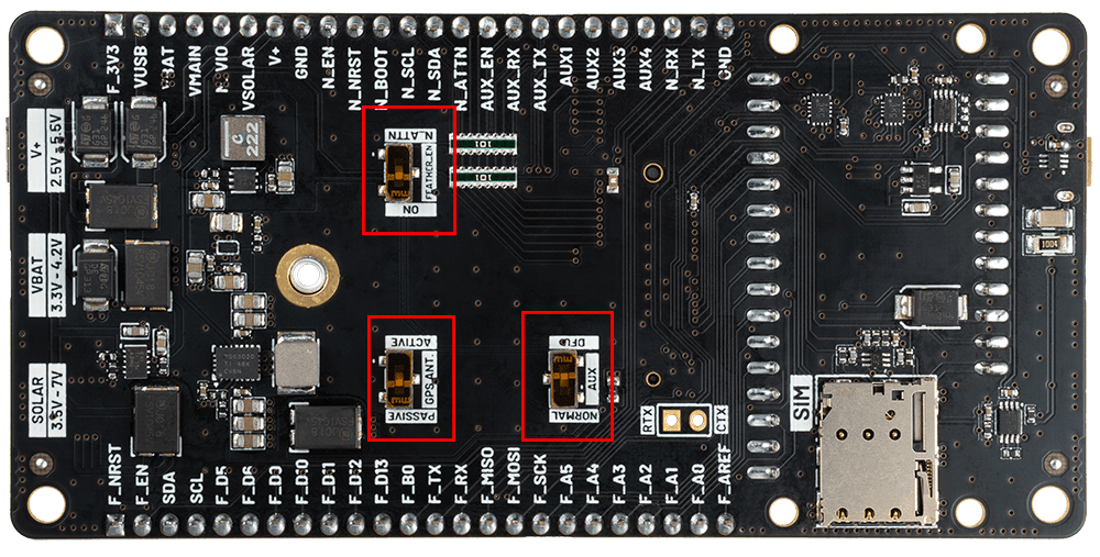
GPS_ANT- When switchedACTIVE, applies 3.9VDC to the center conductor of the Notecard GPS antenna connector to power the low-noise amplifier (LNA) of an active GPS antenna. This switch must bePASSIVE(default) if Notecard is used with a closed-loop, passive GPS antenna! An active antenna is recommended for best performance.AUX- When switchedDFU(default), enables Notecard Outboard Firmware Update with a compatible MCU via the Feather'sF_RX,F_TX,F_B0, andF_NRST. This completely isolates the pins from the external headers, so it is important to note based on the peripherals you use in your design.FEATHER_EN- When switchedON(default), connects theENpin of the 3.6V regulator toN_VIOto keep power all the time. When in theN_ATTNposition connects theENpin of the 3.6V regulator to theATTNpin on the notecard for low power scenarios.
Specifications
Electrical Characteristics
DC Characteristics
| Description | Minimum | Maximum | Unit |
|---|---|---|---|
| Supply Voltage | 2.5 | 5.5 | V |
| Supply Current | 500 | 2000 | mA |
Absolute Maximum Ratings
| Description | Minimum | Maximum | Unit |
|---|---|---|---|
| Storage temperature | -35 | 70 | °C |
Actual values may vary based on local conditions such as atmospheric conditions and distance to the cell tower.
Ordering Information
Design Files
Open source hardware designs for all Notecarriers are maintained in the note-hardware GitHub repository.
Each Notecarrier's versioned folder (for example,
Notecarrier-X/v1.2)
contains the mechanical design resources for that revision, such as
board drawings, dimensional PDFs, Gerber fabrication files, a BOM
spreadsheet, and a STEP (.stp / .step) 3D model suitable for
enclosure design and CAD integration.
Notecarrier Schematics
The following are a set of interactive KiCanvas-powered schematics of the Notecarrier F v1.3.
Notecarrier F
Notecarrier F Feather
Notecarrier F I/O
Notecarrier F Notecard Connectors
Notecarrier F Power Input
Notecarrier F Power Rails
Board Errata
Terms and Conditions
Visit Blues Hardware Terms & Conditions.
Revision History
| Author | Date | Summary |
|---|---|---|
| Ray Ozzie | 2019-2020 | Document drafted |
| John Wiedey | 2020 | Various improvements |
| Sean Taylor | 2020 | Various improvements |
| Zachary J. Fields | 01 OCT 2020 | Updated information and translated to markdown |
| Brandon Satrom | 04 JAN 2021 | Added link to design resources |
| Greg Wolff | 13 JAN 2021 | Added BAT pin information to Notecarrier AF datasheet |
| Brandon Satrom | 07 APR 2022 | Added Notecarrier A information |
| Zachary J. Fields | 20 JUL 2022 | Added Notecarrier F information |
| Zachary J. Fields | 24 OCT 2022 | Added Notecarrier B v2 information |
| Rob Lauer | 28 OCT 2022 | Added versioning for Notecarrier B v1/v2 |
| TJ VanToll | 05 JAN 2023 | Added Notecard Outboard Firmware Update information |
| Rob Lauer | 28 FEB 2023 | Re-labeling Notecarrier B as "Basic" |
| Rob Lauer | 01 MAR 2023 | Added PCB/Mounting Hole Dimensions |
| Rob Lauer | 07 SEP 2023 | Added Notecarrier F v1.3 information |
| Rob Lauer | 16 NOV 2023 | Added Notecarrier Pi v2.0 information |
| Rob Lauer | 14 MAR 2024 | Added Notecarrier B v3.1 and Notecarrier R v1.0 information |
| Rob Lauer | 05 JUN 2024 | Added Notecarrier XS v1.1 information |
| Rob Lauer | 10 JUN 2024 | Added KiCad schematics to A, B, F, and Pi Notecarriers |
| Rob Lauer | 18 JUL 2024 | Added Notecarrier XS v1.2 information |
| Rob Lauer | 22 JUL 2024 | Updated Notecarrier pin descriptions |
| TJ VanToll | 19 AUG 2024 | Added Notecarrier X v1.2, XM 1.2, and XP 3.1 information |
| Rob Lauer | 14 JAN 2026 | Added Notecarrier CX v1.3 information |
| Rob Lauer | 11 FEB 2026 | Added Notecarrier A v2.3 information |
| Rob Lauer | 22 MAY 2026 | Added Notecarrier CX v1.7 information |
Contact Information
Blues Inc.
https://blues.com
50 Dunham Ridge Suite 1650
Beverly, MA 01915
support@blues.com