Blues Notecarrier® Datasheet: Notecarrier B v1.0
Notecarrier A Series
Notecarrier F Series
Notecarrier Pi Hat Series
Notecarrier X Series
Legacy Notecarriers
While this product is still supported, it is no longer available for purchase from the Blues store. We recommend the Notecarrier X and Notecarrier XM as updated alternatives.
Functional Description
Notecarriers are available in multiple form factors to support rapid development across a range of use cases. Depending on the variant, a Notecarrier may prioritize direct host integration, compact size, integrated cellular/WiFi and GNSS antennas, or the ability to be soldered directly into a low-volume production design.
Notecarriers are explicitly designed to bridge the gap between early prototyping and a production-ready Notecard-based solution. In a final product, the Notecard is typically socketed directly onto a custom PCB via an edge connector, alongside the customer's MCU, sensors, and supporting circuitry. While this approach provides maximum flexibility and modularity, it can significantly increase the effort required during initial development and validation.
To simplify this process, Notecarriers expose the Notecard's interfaces through convenient breakout connections and integrate essential supporting circuitry, including power regulation, protection, and signal conditioning. This allows developers to focus on firmware, connectivity, and system behavior without first designing a complete custom carrier board.
Features
- Simple. Provides breadboard compatible pins or solderable mask for direct connections.
- Compatible. Level shifters ensure compatibility with 3.3V or 5V equipment.
- Convenient. Powered by a USB connector (requires 2A supply).
- GPS Ready. Models are either active GPS compatible, or feature a built-in antenna to enable GNSS connectivity.
Compatible Notecards
Due to differences in the physical size of Notecards, certain Notecarriers are only compatible with certain Notecards. The Notecarrier B v1.0 is compatible with:
Package Configuration
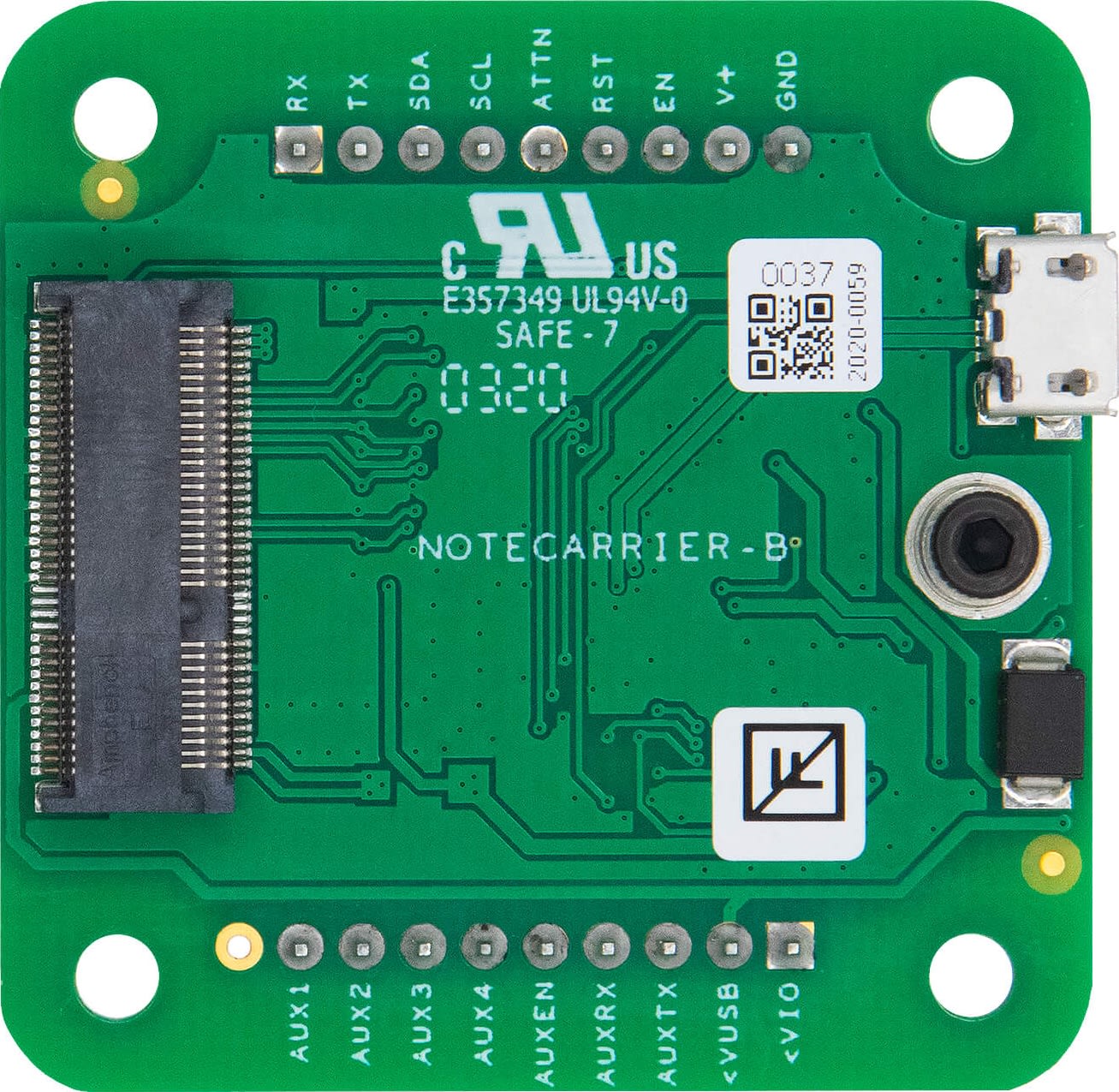
Notecarrier B (Basic) v1.0
Notecarrier B (CARR-B) is designed for building highly customized hardware solutions.
| Front | Back |
|---|---|
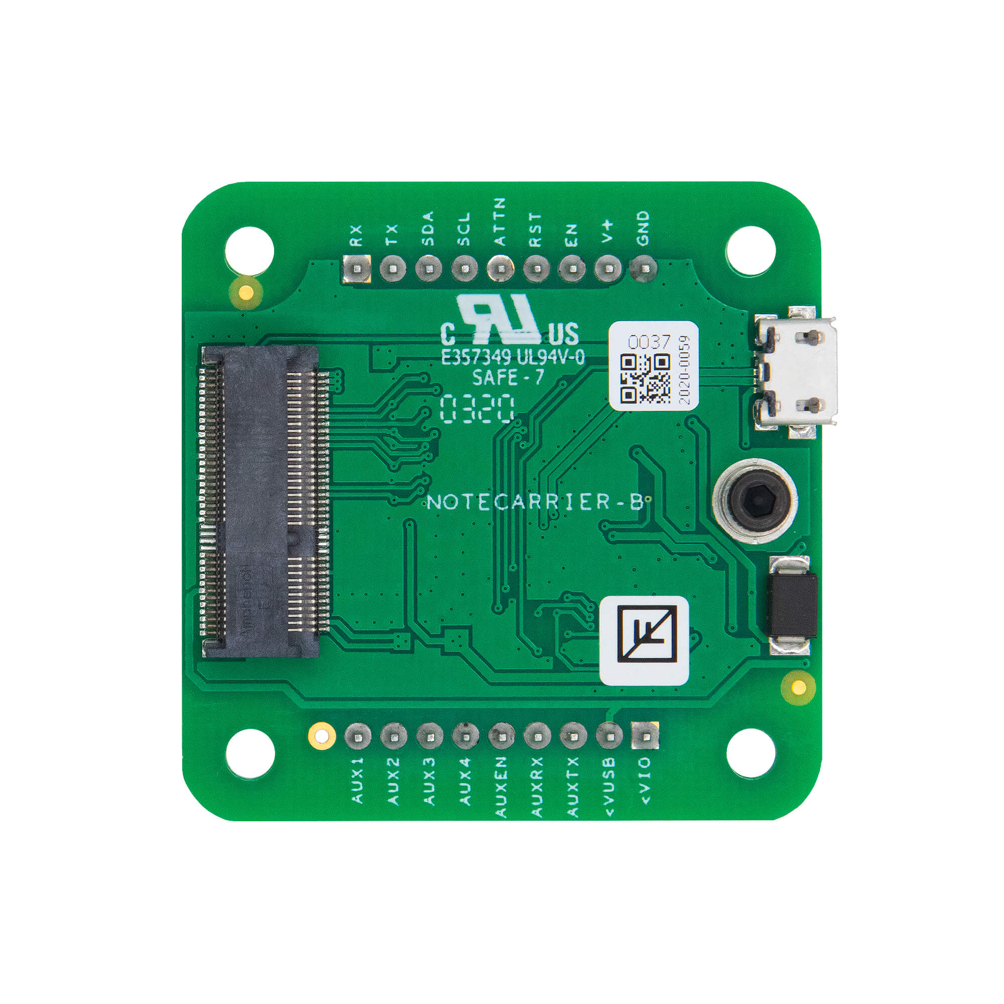 | 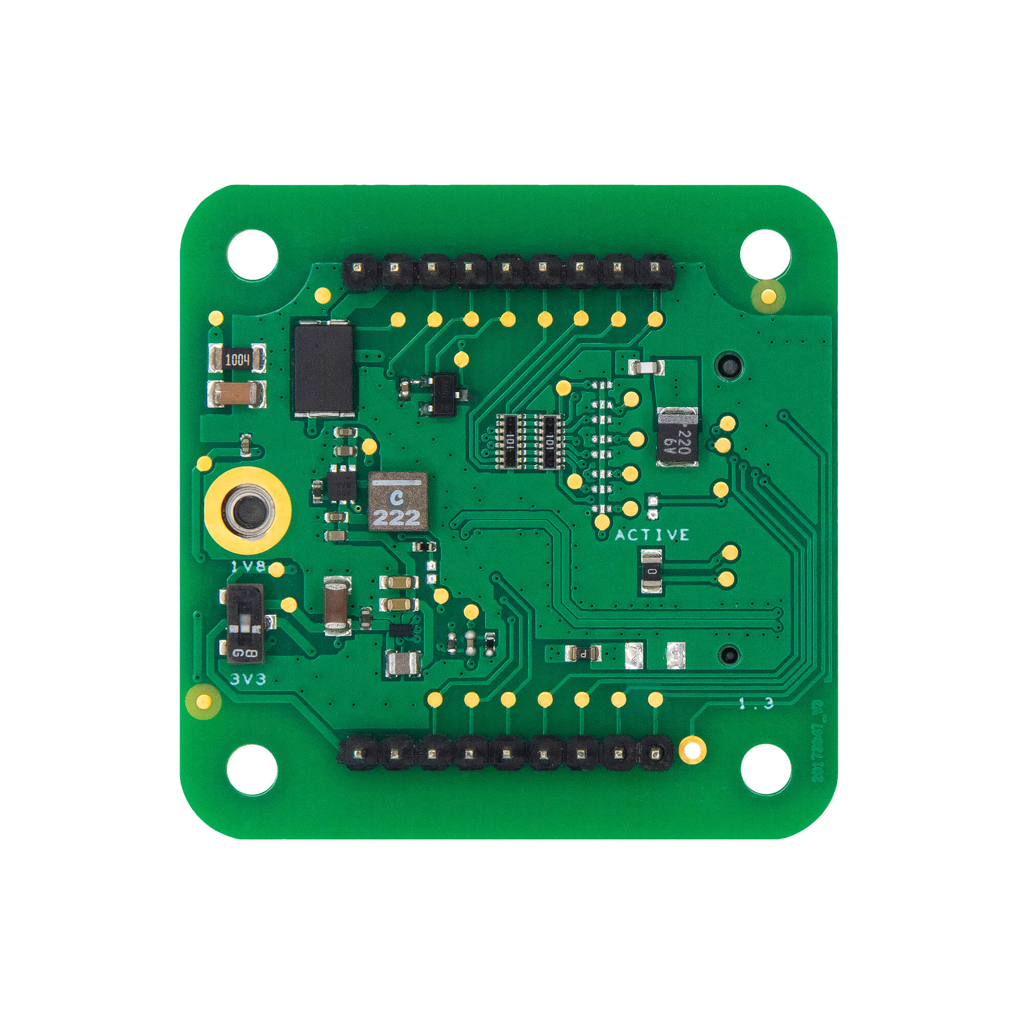 |
-
Notecard edge connector socket and mounting screw receptacle.
-
Micro-USB port to power Notecarrier and provide a USB Serial command interface to Notecard.
-
Requires user provided U.FL cellular/WiFi antenna and optional U.FL active GPS antenna.
-
PCB Dimensions: 45mm x 45mm
-
Center of Mounting Holes: 36mm x 36mm (measured from the edge of the PCB to the center of the furthest mounting hole)
Power Information
All Notecarriers can be powered by connecting directly to the USB port. However, most installations will not have USB power available, so several alternate power options are provided by the various Notecarrier models:
-
applying 2.5-5.5VDC to the
V+pin.Commonly provided via DC power supply or non-rechargeable battery.
Typical USB ports may only be capable of supplying 500 mA of current, which might not be enough to power Notecard during a cellular connection to a GSM network (which can spike to 2A). In this situation, you're advised to supplement power to your Notecarrier with an external source (e.g. a LiPo battery).
GPS (GNSS) Antenna Requirements
All Notecarrier models are designed to support active GPS, and several Notecarrier models provide built-in antennas ready to be connected to a Cellular Notecard using the included u.FL cables.
Active GPS Ready
The Notecarrier B, Notecarrier Pi, and Notecarrier R models do not have integrated GPS antennas, but support active GPS by providing circuitry to enable bias voltage to be supplied.
The Notecarrier B v1.0 has a 0Ω resistor connecting the two pins. The resistor can be removed, allowing you to either utilize a passive GPS antenna, or splice into the circuit and provide your own bias voltage.
Header Descriptions
Notecarrier B Dual 9-pin Headers
| Pin Name | Direction | Usage | Usage | Direction | Pin Name | |
|---|---|---|---|---|---|---|
| AUX1 | IN/OUT | API-selectable modes of operation | UART serial receive request interface (Notecard has onboard 10K pull-up resistors) | IN | RX | |
| AUX2 | IN/OUT | API-selectable modes of operation | UART serial transmit request interface | OUT | TX | |
| AUX3 | IN/OUT | API-selectable modes of operation | I2C data request interface (Notecard has onboard 10K pull-up resistors) | IN/OUT | SDA | |
| AUX4 | IN/OUT | API-selectable modes of operation | I2C clock request interface (Notecard has onboard 10K pull-up resistors) | IN/OUT | SCL | |
| AUXEN | IN | Enable diagnostics | Configurable interrupt signal | OUT | ATTN | |
| AUXRX | IN | High-speed diagnostic interface | For development use only: MUST normally be NC or High Impedance and must never be pulled to GND. A VIO-level pulse of >250ms will reset the Notecard. | IN | RST | |
| AUXTX | OUT | High-speed diagnostic interface | For On/Off switching of customer product. Leave NC or connect to a physical switch or Open Drain output. Notecard will be OFF if pulled to GND. Never apply positive voltage to this pin. | IN | EN | |
| VUSB | IN/OUT | Direct connect to VUSB pin of the USB connector | 2.5-5.5V, < 8µA@5V idle, < 500mA typical, 2A surge max (GPRS) | IN | V+ | |
| VIO | OUT | Digital I/O voltage source with 100mA available | Ground | IN | GND |
Specifications
Electrical Characteristics
DC Characteristics
| Description | Minimum | Maximum | Unit |
|---|---|---|---|
| Supply Voltage | 2.5 | 5.5 | V |
| Supply Current | 500 | 2000 | mA |
Absolute Maximum Ratings
| Description | Minimum | Maximum | Unit |
|---|---|---|---|
| Storage temperature | -35 | 70 | °C |
Actual values may vary based on local conditions such as atmospheric conditions and distance to the cell tower.
Ordering Information
Design Files
Open source hardware designs for all Notecarriers are maintained in the note-hardware GitHub repository.
This Notecarrier's versioned folder contains the mechanical and
electrical design resources for that revision, such as board drawings,
dimensional PDFs, Gerber fabrication files, a BOM spreadsheet, and a
STEP (.stp / .step) 3D model suitable for enclosure design and CAD
integration.
Board Errata
Terms and Conditions
Visit Blues Hardware Terms & Conditions.
Revision History
| Author | Date | Summary |
|---|---|---|
| Ray Ozzie | 2019-2020 | Document drafted |
| John Wiedey | 2020 | Various improvements |
| Sean Taylor | 2020 | Various improvements |
| Zachary J. Fields | 01 OCT 2020 | Updated information and translated to markdown |
| Brandon Satrom | 04 JAN 2021 | Added link to design resources |
| Greg Wolff | 13 JAN 2021 | Added BAT pin information to Notecarrier AF datasheet |
| Brandon Satrom | 07 APR 2022 | Added Notecarrier A information |
| Zachary J. Fields | 20 JUL 2022 | Added Notecarrier F information |
| Zachary J. Fields | 24 OCT 2022 | Added Notecarrier B v2 information |
| Rob Lauer | 28 OCT 2022 | Added versioning for Notecarrier B v1/v2 |
| TJ VanToll | 05 JAN 2023 | Added Notecard Outboard Firmware Update information |
| Rob Lauer | 28 FEB 2023 | Re-labeling Notecarrier B as "Basic" |
| Rob Lauer | 01 MAR 2023 | Added PCB/Mounting Hole Dimensions |
| Rob Lauer | 07 SEP 2023 | Added Notecarrier F v1.3 information |
| Rob Lauer | 16 NOV 2023 | Added Notecarrier Pi v2.0 information |
| Rob Lauer | 14 MAR 2024 | Added Notecarrier B v3.1 and Notecarrier R v1.0 information |
| Rob Lauer | 05 JUN 2024 | Added Notecarrier XS v1.1 information |
| Rob Lauer | 10 JUN 2024 | Added KiCad schematics to A, B, F, and Pi Notecarriers |
| Rob Lauer | 18 JUL 2024 | Added Notecarrier XS v1.2 information |
| Rob Lauer | 22 JUL 2024 | Updated Notecarrier pin descriptions |
| TJ VanToll | 19 AUG 2024 | Added Notecarrier X v1.2, XM 1.2, and XP 3.1 information |
| Rob Lauer | 14 JAN 2026 | Added Notecarrier CX v1.3 information |
| Rob Lauer | 11 FEB 2026 | Added Notecarrier A v2.3 information |
| Rob Lauer | 22 MAY 2026 | Added Notecarrier CX v1.7 information |
| Rob Lauer | 11 JUN 2026 | Added Notecarrier XI v1.4 information |
| Rob Lauer | 16 JUL 2026 | Corrected Notecarrier XI DC specifications and Starnote for Iridium antenna details |
Contact Information
Blues Inc.
https://blues.com
50 Dunham Ridge Suite 1650
Beverly, MA 01915
support@blues.com