
Blues Sparrow™ Datasheet
Sparrow is a low-cost embeddable STM32WLE5-based microcontroller board designed to accelerate the development and deployment of battery-powered IoT solutions, utilizing its onboard LoRa Radio to create a hub-and-spoke network topology.


Sparrow's real power lies in it's sub-gigahertz radio communication. The sub-gigahertz radio band is especially good at travelling long distances in open-air conditions and penetrating barriers and obstacles in closed spaces.
Sparrow is an ideal solution for many projects which would greatly benefit from wireless communication, the cost of adding a cellular or WiFi module to every sensing device is untenable.
Functional Description
Sparrow is based on the STM32WLE5 from STMicroelectronics. The device was built to extend the Notecard's device-to-cloud data pump approach into the low-cost IoT device space. Sparrow has onboard LoRa networking and is designed to serve as a reference toolkit so that developers can quickly get started creating a PoC or Prototype. The default hardware can support several GPIO activities like digital and analog I/O, I2C, UART, and SPI. The firmware provides a plug-n-play model for custom software development, and is built on top of, and controlled by, an underlying, low-power API.
Features
- Features of the ST STM32WLE5+ microcontroller
- 48MHz clock speed
- 256KB Flash
- 64KB of SRAM
- Ultra-low-power comparators, DAC, POR/PDR and timers
- 7x timers
- 2x DMA controller (7 channels each) supporting ADC, DAC, SPI, I2C, LPUART, USART, AES and timers
- Rich analog peripherals (down to 1.62V)
- True random number generator
- Hardware encryption AES 256-bit
- Onboard programmable momentary button (
PAIR) - 3 programmable LEDs (red, blue, green)
- JTAG (SWD capable) debug jack
- BOOT and RESET buttons
- Breadboard compatible 0.1" headers for easy wiring and debugging
Package Configuration
At its core, the Sparrow is a single piece of hardware, which is configured in one of three ways:
Sparrow Gateway
A Sparrow Gateway can be constructed by connecting a Sparrow Essentials Board to a Notecarrier A, using the Qwiic cable and Qwiic connectors. A Sparrow Gateway is designed to be powered via the Notecarrier A (not the Sparrow Essentials Board), and the DIP switch on the Notecarrier A must be set to 3V3.

Sparrow Reference Sensor Node
Just add batteries and go. The reference sensor board comes with an integrated BME280 and PIR sensor. Once this device has been paired with a Gateway, then this device will start automatically capturing real data that you can work with while configuring your Notehub project.
It comes populated with the following items:
- Bosch BME280 (temp/humidity/pressure) Sensor
- PIR (motion) Sensor
- Cortex Debug Connector
- RESET/BOOT Buttons
- (2x) AAA Battery Holder

Sparrow Essentials Board
Designed for rapid prototyping, it comes populated with the following items:
- Cortex Debug Connector
- Female Pin Headers
- RESET/BOOT Buttons
- LiPo JST Connector
- Qwiic Connector
- Coin-cell Battery Holder

Unified Firmware, Split Personality
All the different Sparrow configurations run from the same firmware. Once the firmware boots, it looks for a Notecard (of any flavor) on the I2C bus. If the firmware finds one, then it decides that it is wired up as part of a Sparrow Gateway. If not, it then looks for a BME280 environmental sensor on the I2C bus. If found, then the firmware decides it is a Reference Sensor Board. However, if it finds neither, then the firmware defaults to behaving as an Essentials Board.
Pin Information
The following tables contain pin definition mappings between the Sparrow headers and the pins from the STM32LE55 (the core MCU).
STM32 Mapping to Sparrow Header
| Pin # | Header | Pin Description | Pin # | Header | Pin Description | |
|---|---|---|---|---|---|---|
| NRST | RST# | RESET Button | PA7 | MOSI | Main Out / Secondary In | |
| PH3-BOOT0 | BOOT | BOOT Button | PA6 | MISO | Main In / Secondary Out | |
| VSS_EP | GND | Ground | PA5 | SCK | SPI Clock | |
| PA2 | LPTX | Low-Power UART Transmit | PA4 | CS | Chip Select | |
| PA3 | LPRX | Low-Power UART Receive | PA11 | SDA | I2C Data | |
| PB2 | A1 | Analog Pin 1 | PA12 | SCL | I2C Clock | |
| PA10 | A2 | Analog Pin 2 | PA1 | BLU | Blue LED | |
| PA15 | A3 | Analog Pin 3 | PA0 | RED | Red LED | |
| PA13 | SWDIO | Single-Wire Debug I/O | PB12 | GRN | Green LED | |
| PA14 | SWCLK | Single-Wire Debug Clock | PB7 | RX | UART Receive | |
| PC13 | BTN# | PAIR Button | PB6 | TX | UART Transmit | |
| VDD | VIO | Logic-level Voltage | -- | BAT | Direct Battery Voltage |
Setting a Frequency Plan
All Sparrow boards have four DIP switches that control the frequency ranges that the device's LoRa radio operates within.
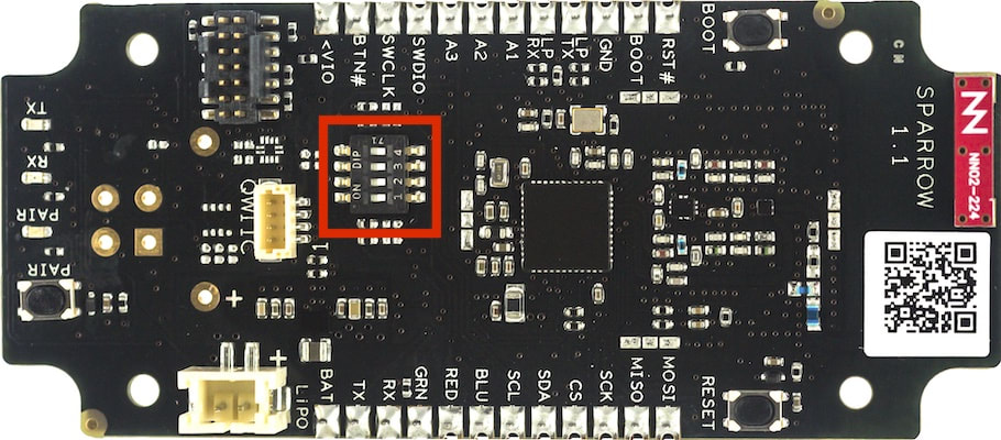
The pins allow you to set your board to multiple common LoRa frequency plans using the configuration shown below. If you're unsure what plan to use in your region, this guide to LoRa regional parameters is a good reference.
| Pin 1 | Pin 2 | Pin 3 | Pin 4 | Frequency Plan |
|---|---|---|---|---|
| OFF | OFF | OFF | OFF | US915 |
| OFF | OFF | OFF | ON | AU915 |
| OFF | OFF | ON | OFF | IN865 |
| OFF | ON | OFF | OFF | KR920 |
| OFF | ON | OFF | ON | EU433 |
| OFF | ON | ON | OFF | RU864 |
| ON | OFF | OFF | OFF | AS923 |
| ON | OFF | OFF | ON | CN470 |
| ON | OFF | ON | OFF | EU868 |
 note
noteRemember to set the switches on both your Sparrow Essentials Boards and Reference Sensor Boards, as the frequency plans on each must match for the boards to communicate successfully.
For production hardware we recommend setting the DIP switches at your product's factory to reflect the destination of the device. Alternatively, you may populate R27 / R28 / R29 / R30 (see schematic below) with zero-Ohm resistors as necessary to simulate DIP switches that are ON.

As one final option, the Sparrow firmware allows you to set a LoRa frequency in
a way that overrides the hardware switches. If you're interested in this option see
our guide on running custom Sparrow firmware,
and then set the RF_FREQ value here
to your desired frequency.
Specifications
Electrical Characteristics
DC Characteristics
| Description | Minimum | Maximum | Unit |
|---|---|---|---|
BAT Supply Voltage | 2.8 | 5.5 | V |
| Supply Current | 0.5 | 2.0 | A |
Absolute Maximum Ratings
| Description | Minimum | Maximum | Unit |
|---|---|---|---|
| Storage temperature | -35 | 70 | °C |
Ordering Information
- Please visit the Sparrow product page for ordering information.
Design Files
Open source hardware designs for the Sparrow and all Blues Hardware are maintained in the note-hardware GitHub repository, including:
- Sparrow Essentials board BOM, schematic, 3D model, and Gerbers
- Sparrow Reference Sensor board BOM, schematic, 3D Model, and Gerbers
Board Errata
-
Some Sparrow Reference Sensor boards with a
1.1marking on the serigraphy have an improperly mounted Cortex Debug connector which prevents using an external programmer (such as the STLINK-V3MINI included with the Sparrow Dev Kit) for interfacing with the board. A properly-mounted connector, as depicted below, has the single tab side of the debug connector oriented to the edge of the board. On improperly-mounted boards, this connector is reversed, with the double tab side oriented to the edge of the board. Please contact Blues if you wish to request a replacement.
Qualifications and Approvals
| Certification | Date |
|---|---|
| FCC | Pending |
Terms and Conditions
Visit Blues Hardware Terms & Conditions.
Revision History
| Author | Date | Summary |
|---|---|---|
| Zachary J. Fields | 10 AUG 2022 | Document drafted |
| TJ VanToll | 02 NOV 2022 | Added frequency plan configuration |
| Brandon Satrom | 30 JAN 2023 | Added errata for Reference Sensor Cortex Debug connector |
Contact Information
For other questions about the Sparrow, visit the Blues Forum.
Blues Inc.
https://blues.com
50 Dunham Ridge Suite 1650
Beverly, MA 01915
support@blues.com