
Host Wiring Guide
In this tutorial you'll learn how to wire a Notecard to a host microcontroller (MCU) or single-board computer (SBC).
Background
In the Notecard Quickstart you learned how to communicate with a Notecard using the In-Browser Terminal. While the In-Browser Terminal is useful for learning and experimentation, most production connected products use a Notecard alongside a host microcontroller (MCU) or single-board computer (SBC). In this setup, the host runs the device's application logic, while the Notecard handles connectivity.

For this to architecture to work, the host and Notecard must be able to communicate with each other. The Notecard provides three interfaces for performing communication: I2C, UART, and USB. These interfaces provide the transport layer for Notecard's JSON API—allowing a host to send JSON requests and receive JSON responses.
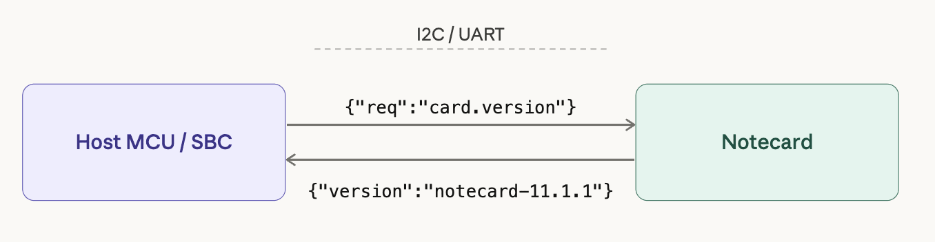
In most connected products, a host MCU or SBC communicates with a Notecard in firmware using I2C or UART. Before that firmware can communicate with the Notecard, the two must be physically wired together.
In this guide you’ll learn how to correctly wire a host to a Notecard for both interfaces. Once the wiring is complete you'll be ready to write host firmware that communicates with the Notecard in future tutorials.
What You Need
Before continuing make sure you have:
- A Notecard installed in a Notecarrier.
- The Notecarrier provides power regulation, and exposes Notecard's pins for wiring.
- If your Notecarrier came with loose header pins, you'll need to solder them on with a soldering iron to expose the required Notecard pins before continuing.
- If, in the future, you wish to build a custom carrier to connect a Notecard and a host, make sure to read through the Serial Notecard Request Interfaces section of the Notecard Carrier Design Guide.
- A host MCU or SBC of your choice.
- Notecard works with virtually any host MCU or SBC.
- If you're not sure what host to use, Blues Cygnet is a good place to start—it's made by Blues, and we document a variety of ways to write firmware with it.
- Jumper wires.
 note
noteSome Notecarriers automatically handle the required wiring between a Notecard and a host, removing the need to perform the manual wiring discussed in this guide.
-
The Notecarrier F automatically connects power and the required communication lines between a Notecard and Feather-formatted hosts, such as the Blues Swan or Blues Cygnet.
-
The Notecarrier Pi Hat automatically connects power and the required communication lines between a Notecard and a Raspberry Pi.
-
The Notecarrier CX includes a Notecard and a host MCU on a single board, and also has the required communication lines between the two in place.
Choosing Your Interface
Notecard supports two primary communication interfaces for host microcontrollers.
-
I2C is a two-wire bus protocol that lets multiple devices share the same clock and data lines. Notecard's I2C interface is available at address
0x17, but can be reconfigured using acard.iorequest. -
UART is a simple point-to-point serial protocol available on virtually every microcontroller. Notecard's Serial UART interface is fixed at a baud rate of 9600, with eight data bits, no parity bit, and one stop bit (
9600/N-8-1).
I2C is typically the default choice for microcontroller-based designs, but UART can be a solid alternatively when your project calls for it. Here are some points to consider.
noteRegardless of which interface you choose, your firmware will send the same JSON requests and receive the same JSON responses from Notecard.
When to Use I2C
Choose I2C when:
- Your host MCU has dedicated hardware I2C pins (
SDA,SCL). - You want the simplest possible wiring.
- You want to share the bus with other I2C devices (sensors, displays, etc.).
Because many sensor modules use I2C, using the same bus for your peripherals and Notecard can often simplify wiring in hardware designs.
noteNotecard uses a Serial-Over-I2C protocol that allows developers to handle JSON requests and responses in a similar manner as a direct serial connection. Notecard's firmware libraries abstract the implementation details of this protocol from you, but if you're curious you can read how it works in Serial-Over-I2C Protocol.
When to Use UART
Choose UART when:
- Your host MCU lacks dedicated I2C hardware.
- Your host has available UART pins (
TXandRX). - You prefer a simpler point-to-point connection.
Once you've selected the protocol you wish to use, see the sections below for how to wire your Notecard to your host.
noteOther Interfaces
Notecard also provides interfaces for communicating over AUX UART or USB, but these are intended to be used for debugging purposes, and not as host interfaces.
Wiring with I2C
When using I2C, the host and Notecard communicate using two signal lines: a data
line (SDA) and a clock line (SCL). Both devices must also share a common
ground reference.
In most designs, you can connect the host's I2C pins directly to the Notecard's I2C pins (exposed via the Notecarrier).
| Notecard Pin | Host Pin | Description |
|---|---|---|
SDA | SDA | I2C data line |
SCL | SCL | I2C clock line |
GND | GND | Shared ground reference |
Note: Notecard includes onboard 10K pull-up resistors on
SDAandSCL, so you typically do not need to add external pull-ups when wiring a host directly to a Notecarrier.
For example, the following shows an example of wiring a Blues Cygnet host to a Notecarrier A using an I2C connection.
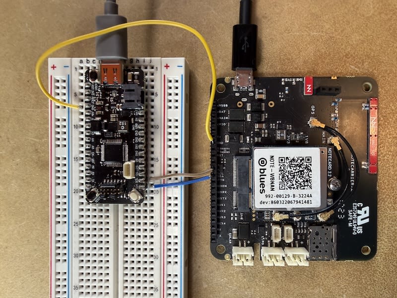
During initial testing we recommend that you power your host and Notecard independently, either with LiPo batteries or with USB power. In the image above both the Blues Cygnet host and Notecard are powered via USB cables.
Once you're confident your host and Notecard are communicating correctly (which you'll verify in Next Steps), you will likely wish to power your host from your Notecarrier.
Wiring with UART
When using UART, the host and Notecard communicate using two signal lines: a
transmit line (TX) and a receive line (RX). Both devices must also share a
common ground reference.
In most designs you will connect the host's UART pins directly to the
corresponding Notecard pins (exposed via the Notecarrier). Note the standard
UART crossover: the Notecard's TX connects to the host's RX, and the
Notecard's RX connects to the host's TX.
| Notecarrier Pin | Host Pin | Description |
|---|---|---|
TX | RX | Notecard transmit / host receive |
RX | TX | Notecard receive / host transmit |
GND | GND | Shared ground reference |
For example, the following shows an example of wiring a Blues Cygnet host to a Notecarrier A using a UART connection.
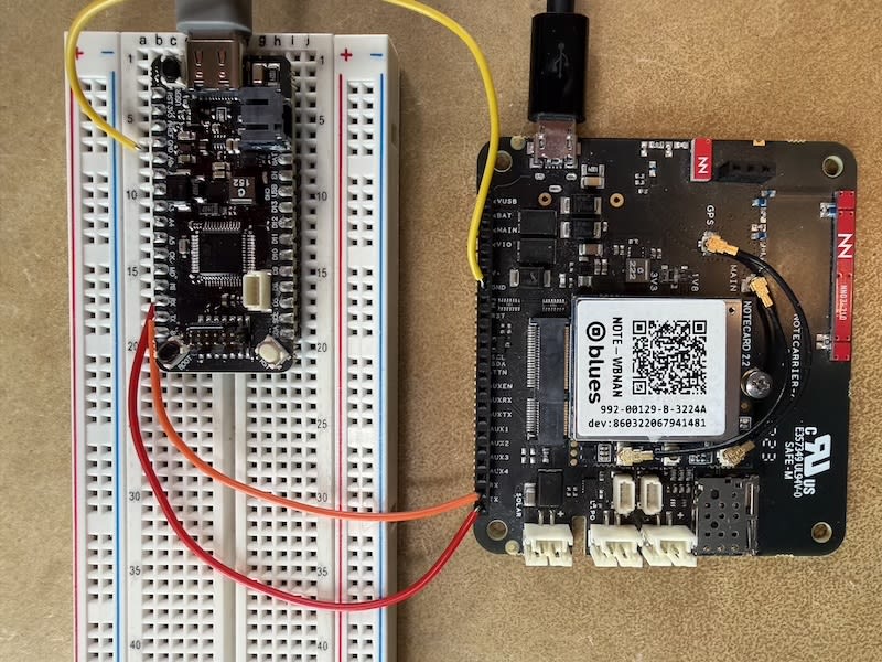
During initial testing we recommend that you power your host and Notecard independently, either with LiPo batteries or with USB power. In the image above both the Blues Cygnet host and Notecard are powered via USB cables.
Once you're confident your host and Notecard are communicating correctly (which you'll verify in Next Steps), you will likely wish to power your host from your Notecarrier.
Next Steps
With your host and Notecard physically connected, you have everything in place to start writing firmware. The next step is to put that wiring to the test.
Our Collecting Sensor Data tutorial walks you through writing host firmware that communicates with the Notecard over the interface you just wired up. In the tutorial you'll gather sensor data on your host, send it to the Notecard using its JSON API, and then see that data flow into Notehub.