Notecard Outboard Firmware Update
Watch a video of this tutorial
An increasing number of MCUs produced in the last decade are shipped with their
primary bootloaders in ROM, unmodifiable by any user operation. On these
devices, including all modern ST Microelectronics and Espressif
microcontrollers, when a RESET pin is asserted, the device enters this ROM
bootloader. The bootloader can load and execute code from a variety of sources
including Flash, RAM, UART, USB, I2C, or SPI. This ROM bootloader's behavior is
controlled by actively probing those I/O ports and by sampling the state of
"strapping pins" or specially locked "boot option bytes" in flash.
These manufacturer-provided ROM bootloaders present new alternatives for hardware designers - specifically, to perform firmware updates in a manner that is far more flexible in terms of language and RTOS, and far less vulnerable to inadvertent programming bugs.
Blues Notecard takes advantage of these ROM bootloaders to update host firmware "from the outside," without relying on the firmware currently running on the host MCU to carry out the update. This capability is called Notecard Outboard Firmware Update, commonly abbreviated "ODFU" or "NOFU".
Because the update is performed from the outside, it does not depend on the host's existing firmware being functional. It does, however, require that the Notecard be configured for Outboard Firmware Update ahead of time, with the correct card.dfu (and, where applicable, card.aux) settings for your specific Notecarrier and host. If these settings aren't applied before deployment, a remote update can fail, and recovery may require physical access to the device. See Quickstart for Blues Hardware for the known-working settings for common Blues hardware combinations.
Notecard Outboard Firmware Update can update firmware regardless of RTOS or language, and can be used to switch between them, even modifying flash memory layout and partitioning any time after-the-fact, at the developer's discretion.
-
The maximum size of a host binary file is 1.5 MB for all Notecards, with the following exceptions:
- Notecard WiFi v2 has a maximum of 900KB.
- Notecard for LoRa does not support OTA host or Notecard firmware updates.
-
When a firmware update is requested via Notecard Outboard Firmware Update, Notehub sets the device's
_fwenvironment variable to the intended firmware version. On subsequent syncs, Notehub will replace any sideloaded (non-OTA) firmware that does not match the value in_fw. To prevent this behavior, users must manually delete the_fwenvironment variable before syncing if they intend to keep non-OTA firmware installed.
How It Works
By using the Notecard in conjunction with a modern MCU with a ROM bootloader, you can achieve a far more robust form of firmware update.
At a high-level the process works as follows:
- You ensure your hardware is using the required wiring.
- You enable Notecard Outboard Firmware Update on your Notecard.
- You build your firmware image file.
- You upload your firmware on Notehub.
- The Notecard downloads the firmware, verifies it, and performs the update.
Let's first look at how you can implement these steps quickly with Blues hardware, and then take a detailed look at how to implement these steps using other compatible hardware options.
Quickstart for Blues Hardware
This quickstart is provided for users of:
- A Notecarrier CX
- A Notecarrier F with a connected Blues Cygnet or Swan
Required Wiring for Blues Hardware
Blues Notecarrier CX and F are both pre-configured to work with Notecard Outboard Firmware Update, so no additional wiring is required.
Enable Notecard Outboard Firmware Update with card.dfu
The card.dfu request you
send depends on which Notecarrier you're using, because each one routes the
host's BOOT, RESET, and UART lines to a different set of Notecard pins.
Notecarrier CX
Notecarrier CX programs its onboard host through the Notecard's dedicated
ALT_DFU pins, so set "mode":"altdfu":
{
  "req": "card.dfu",
  "name": "stm32",
  "on": true,
  "mode": "altdfu"
}
Notecarrier F (with Swan or Cygnet)
Notecarrier F connects the Feather's BOOT, RESET, and UART lines to the
Notecard's AUX pins (AUX3, AUX4, AUX_TX, and AUX_RX), not the
dedicated ALT_DFU pins. Use the default AUX pin path by setting
"mode":"aux" (or by omitting mode entirely):
{
  "req": "card.dfu",
  "name": "stm32",
  "on": true,
  "mode": "aux"
}
Then make sure nothing else has claimed those AUX pins by setting
card.aux to off:
{
  "req": "card.aux",
  "mode": "off"
}
Build Your Firmware
Generate a firmware binary for your host using your tooling of choice and
identify the location of the .bin output file. If you need help with this
step, consult this section below.
Next, install the Notecard CLI to use a capability called "binpack". Binpack is used to create a thin wrapper around your binary, which offers protection and enables optimization of binary installation.
Open up a terminal, navigate to the directory of your binary, and issue this command:
notecard -binpack stm32 0x8000000:myfirmware.binOnce binpack runs, you'll see output like this:
2023-03-06-195216.binpack now incorporates 1 files and is 100980 bytes (14% saved because of compression):

HOST: stm32
LOAD: firmware.bin,0x08000000,0x1c178,0x1c178
Upload Binpacked Binary to Notehub
Finish the process by following the instructions provided below to upload the newly binpacked binary to Notehub and deliver it to your devices.
Required Wiring
To take advantage of Notecard Outboard Firmware Update you must lay out several
connections between the Notecard's AUX (or ALT_DFU) pins and your own host
MCU's NRST, BOOT, and UART pins.
The following carriers have the required wiring available out of the box, and are ready-made for using Notecard Outboard Firmware Update:
If you're not using a ready-made carrier, you can still utilize Outboard Firmware Update on most modern STM32 and ESP32 hosts. Below, examples are shown for the generic pinout required for UART DFU, typically found on the ESP32 and STM32 hosts. Please refer to your specific host's datasheet for the correct pinout required for UART DFU.
Pin Mapping Table
| Notecard | Generic MCU | ESP32 | STM32 |
|---|---|---|---|
ALT_DFU_ACTIVE (or AUX1 - see note #3 below) | -- | -- | -- |
ALT_DFU_BOOT (or AUX3) | B0 | IO0 | BOOT0 |
ALT_DFU_RESET (or AUX4) | NRST (an active LOW reset line) | EN | NRST |
ALT_DFU_RX (or AUXRX) | TX | TXD0 | USART1_TX |
ALT_DFU_TX (or AUXTX) | RX | RXD0 | USART1_RX |
GND | GND | GND | GND |
Pin Mapping Considerations
-
The
ALT_DFUpins are available on modern versions of Notecard Cellular, Notecard Cell+WiFi, and Notecard WiFi. When in doubt, check the Pin Information section of your Notecard's datasheet. -
Notecards that do not have
ALT_DFUpins must use theAUXpins as listed above. -
In the context of Notecard Outboard Firmware Update, the Notecard's
AUX1pin represents whether a firmware update is not in progress (NDFU).The
AUX1pin is not enabled by default. It must be explicitly enabled by issuing acard.auxrequest and specifying"mode":"dfu".The
AUX1pin has no corresponding pin on the Host MCU; instead, it is used to drive an external multiplexor (or mux).AUX1is activeLOWwhen a DFU is in progress, otherwise it remainsHIGH. See Using DFU Mode for more information. -
If you're using a sensor that requires serial TX/RX and have enabled Notecard Outboard Firmware Update using AUXTX/AUXRX, you must connect the sensor to an alternative serial bus. The following options are available using the specified pins:
HardwareSerial Serial2(A0,A3); HardwareSerial Serial3(A5,A4); -
When developing with an ESP32-S3 host, avoid using
GPIO3,GPIO45, andGPIO46at all costs. These pins are used to control the strapping behavior of the host, and can cause issues with boot behavior. If you must use these pins, ensure that you only drive them after the host has booted.
-
Notecard Outboard Firmware Update only functions while the Notecard is in
continuousorperiodicmode (set via the hub.set API). -
Notecard Outboard Firmware Update is only compatible with the following card.aux modes:
dfuneo-monitortrack-neo-monitoroff
Notecard Outboard Firmware Update Examples
The following examples show how to use Notecard Outboard Firmware Update from each supported host platform.
- Arduino
- An Arduino sketch that enables Notecard Outboard Firmware Update on an STM32 host such as the Swan, Cygnet, or STM32F405 Feather.
- CircuitPython
- A CircuitPython example that enables Notecard Outboard Firmware Update on the Swan and updates it over-the-air.
- Zephyr
- A Zephyr example for STM32 hosts (Swan and Cygnet).
- nRF52840 / MCUboot
- An example for the Adafruit Feather nRF52840 (Express and Sense) using MCUboot with the Nordic Connect SDK.
Enabling Notecard Outboard Firmware Update
In order to use Notecard Outboard Firmware Update you must first configure your Notecard to receive firmware updates.
Firmware is uploaded to Notehub, then downloaded from Notehub to your Notecard, and finally flashed to your host MCU. Each of these steps must be enabled in order for Notecard Outboard Firmware Update to work.
Notehub to Notecard
Downloading firmware from Notehub to the Notecard is enabled by default.
However, you may wish to ensure the transfer is enabled by explicitly sending
a dfu.status request to
the Notecard.
{
  "req": "dfu.status",
  "on": true
}J *req = NoteNewRequest("dfu.status");
JAddBoolToObject(req, "on", true);
NoteRequest(req);req = {"req": "dfu.status"}
req["on"] = True
rsp = card.Transaction(req)The dfu.status request also accepts a version argument you can use to report
more information about your firmware to Notehub. The version argument accepts
a simple string (e.g. "1.0.0.0"), and a richer object with detailed information
about the firmware running on your device. The richer object is recommended and
an example is shown below.
{
  "req": "dfu.status",
  "on": true,
  "version": "{\"org\":\"myorg\",\"product\":\"My Product\",\"description\":\"My description\",\"version\":\"1.0.0\",\"built\":\"Jan 01 2025 01:02:03\",\"ver_major\":1,\"ver_minor\":0,\"ver_patch\":0,\"ver_build\":0,\"builder\":\"My Name\"}"
}J *req = NoteNewRequest("dfu.status");
JAddBoolToObject(req, "on", true);
JAddStringToObject(req, "version", "{\"org\":\"myorg\",\"product\":\"My Product\",\"description\":\"My description\",\"version\":\"1.0.0\",\"built\":\"Jan 01 2025 01:02:03\",\"ver_major\":1,\"ver_minor\":0,\"ver_patch\":0,\"ver_build\":0,\"builder\":\"My Name\"}");
NoteRequest(req);req = {"req": "dfu.status"}
req["on"] = True
req["version"] = "{\"org\":\"myorg\",\"product\":\"My Product\",\"description\":\"My description\",\"version\":\"1.0.0\",\"built\":\"Jan 01 2025 01:02:03\",\"ver_major\":1,\"ver_minor\":0,\"ver_patch\":0,\"ver_build\":0,\"builder\":\"My Name\"}"
rsp = card.Transaction(req)The following code has an implementation of a firmwareVersion function that
generates the version argument in the expected format.
// C Helpers to convert a number to a string
#define STRINGIFY(x) STRINGIFY_(x)
#define STRINGIFY_(x) #x

// Definitions used by firmware update
#define PRODUCT_ORG_NAME      "My Organization"
#define PRODUCT_DISPLAY_NAME  "My Product"
#define PRODUCT_FIRMWARE_ID   "my-product"
#define PRODUCT_DESC          "My description"
#define PRODUCT_MAJOR         1
#define PRODUCT_MINOR         0
#define PRODUCT_PATCH         0
#define PRODUCT_BUILD         0
#define PRODUCT_BUILT         __DATE__ " " __TIME__
#define PRODUCT_BUILDER       "My Name"
#define PRODUCT_VERSION       STRINGIFY(PRODUCT_MAJOR) "." STRINGIFY(PRODUCT_MINOR) "." STRINGIFY(PRODUCT_PATCH)

// This is a product configuration JSON structure that enables the Notehub to recognize this
// firmware when it's uploaded, to help keep track of versions and so we only ever download
// firmware builds that are appropriate for this device.
#define QUOTE(x) "\"" x "\""
#define FIRMWARE_VERSION_HEADER "firmware::info:"
#define FIRMWARE_VERSION FIRMWARE_VERSION_HEADER         \
    "{" QUOTE("org") ":" QUOTE(PRODUCT_ORG_NAME)         \
    "," QUOTE("product") ":" QUOTE(PRODUCT_DISPLAY_NAME) \
    "," QUOTE("description") ":" QUOTE(PRODUCT_DESC)     \
    "," QUOTE("firmware") ":" QUOTE(PRODUCT_FIRMWARE_ID) \
    "," QUOTE("version") ":" QUOTE(PRODUCT_VERSION)      \
    "," QUOTE("built") ":" QUOTE(PRODUCT_BUILT)          \
    "," QUOTE("ver_major") ":" STRINGIFY(PRODUCT_MAJOR)  \
    "," QUOTE("ver_minor") ":" STRINGIFY(PRODUCT_MINOR)  \
    "," QUOTE("ver_patch") ":" STRINGIFY(PRODUCT_PATCH)  \
    "," QUOTE("ver_build") ":" STRINGIFY(PRODUCT_BUILD)  \
    "," QUOTE("builder") ":" QUOTE(PRODUCT_BUILDER)      \
    "}"

// Return the firmware's version, which is both stored within the image and which is verified by DFU
const char *firmwareVersion() {
    return &FIRMWARE_VERSION[sizeof(FIRMWARE_VERSION_HEADER)-1];
}J *req = NoteNewRequest("dfu.status");
JAddBoolToObject(req, "on", true);
JAddStringToObject(req, "version", firmwareVersion());
NoteRequest(req);Once provided, the version information you provide displays in the Notehub user interface on your device's Host Firmware tab.

Notecard to Host MCU
To allow the Notecard to flash the host MCU with the downloaded binary use the
card.dfu request, setting
"name" to the architecture of the host (e.g. stm32, esp32, mcuboot) and
"on" to true.
{
  "req": "card.dfu",
  "name": "<host_mcu>",
  "on": true
}J *req = NoteNewRequest("card.dfu");
JAddStringToObject(req, "name", "<host_mcu>");
JAddBoolToObject(req, "on", true);
NoteRequest(req);req = {"req": "card.dfu"}
req["name"] = "<host_mcu>"
req["on"] = True
card.Transaction(req)Newer Notecards expose a dedicated set of ALT_DFU pins in addition to the
shared AUX pins (see Required Wiring). On these Notecards —
which include all versions of Notecard Cell+WiFi, non-legacy versions of
Notecard Cellular, and Notecard WiFi v2 — the card.dfu request also accepts a
mode argument that controls which set of pins is used for Notecard Outboard
Firmware Update:
"mode":"altdfu"uses the dedicatedALT_DFUpins. This is required when your Notecard is wired to the host through itsALT_DFUpins, as on the Notecarrier CX."mode":"aux"(the default) uses the sharedAUXpins. This is the correct setting for the Notecarrier F (see Required Wiring).
If your host is wired to the shared AUX pins (including on the Notecarrier F),
you can omit mode entirely or set "mode":"aux". If your Notecard is wired to
the host through its dedicated ALT_DFU pins (such as on the Notecarrier CX),
include "mode":"altdfu" as shown below.
{
  "req": "card.dfu",
  "name": "<host_mcu>",
  "on": true,
  "mode": "altdfu"
}J *req = NoteNewRequest("card.dfu");
JAddStringToObject(req, "name", "<host_mcu>");
JAddBoolToObject(req, "on", true);
JAddStringToObject(req, "mode", "altdfu");
NoteRequest(req);req = {"req": "card.dfu"}
req["name"] = "<host_mcu>"
req["on"] = True
req["mode"] = "altdfu"
card.Transaction(req)Using STM32 Host with Boot Pin Inverted
By default, the Notecard expects STM32-based hosts to have a boot pin that's assumed to be active high, where high-logic voltage indicates Boot Mode, and low-logic voltage indicates Normal Mode.
If you are using an STM32-based host with a boot pin that's instead assumed
to be active low, you can send the card.dfu request a "name" of "stm32-bi"
(where "bi" stands for boot inverted), to ensure Notecard Outboard Firmware
Update works correctly.
{
  "req": "card.dfu",
  "name": "stm32-bi",
  "on": true
}
Using a Host with MCUboot Support
Support for Notecard Outboard Firmware Update on hosts that use the MCUboot bootloader (e.g. nRF52840) was introduced in Notecard firmware v5.3.1.
{
  "req": "card.dfu",
  "name": "mcuboot",
  "on": true
}
Please consult this example for implementation details.
Now that you've enabled Notecard Outboard Firmware Update, you next need to prepare your firmware image file.
Building a Firmware Image File
In this section you'll learn how to build a firmware image file for use with Notecard Outboard Firmware Update.
Generate/Collect Binaries for your Target Platform
Building your firmware binary itself is not unique to Notecard Outboard Firmware
Update. This is the standard creation of a firmware binary that will be deployed
to a target device. The only thing new is we will be operating on this
binary (.bin) file instead of immediately installing it on the target device.
When using the Arduino IDE, you can find the location of the binary in the final logs of the compilation step, as illustrated below. (If you're not seeing the path in your log, enable verbose logging in your Arduino IDE's settings and build again.)

Looking in the folder specified, we will find the .bin file alongside the
.elf file mentioned in the build output.

In PlatformIO the built .bin file appears in your project's .pio/build
folder.

Wrapping Binaries Using Binpack
Binpack Overview
The binpack utility is provided through the
Notecard CLI. Binpack is used to create a thin
wrapper around your binary, which both offers protection and enables
optimization of binary installation.
Binpack Construction
The syntax of the binpack utility is as follows:
notecard -binpack <host_arch> <memory_addr>:<binary.bin> [<memory_addr>:<binary.bin> ...]<host_arch>- Replace with the architecture of your host MCU. (See thecard.dfurequest'snameargument for a list of possible values.)<memory_addr>- The address* where the binary should be installed.<binary.bin>- The binary file to package.
* Minimally, the page of memory associated with the address provided will be completely erased and rewritten.
Targeting an STM32 device and performing binpack on the Arduino example
provided above would result in the following syntax:
notecard -binpack stm32 0x8000000:Example1_NotecardBasics.ino.binAfter the command executes, you will see output similar to the following:
2022-10-20-205150.binpack now incorporates 1 files and is 28999 bytes:

HOST: stm32
LOAD: Example1_NotecardBasics.ino.bin,0x08000000,0x70a8,0x70a8
INFO: firmware::info:{"org":"My Organization","product":"My Product","description":"My description","firmware":"my-product","version":"1.0.0","built":"Dec 20 2024 10:49:23","ver_major":1,"ver_minor":0,"ver_patch":0,"ver_build":0,"builder":"My Name"}
Alternatively, targeting an ESP32 device and performing binpack on the
Arduino example provided above would result in the following syntax:
notecard -binpack esp32 0x10000:Example1_NotecardBasics.ino.binThe two changes worth noting are...
- The
<host_arch>parameter changed fromstm32toesp32 - The
<memory_addr>parameter changed from0x8000000to0x10000
If using the ESP32C3, the <memory_addr> parameter should be set to
0x00000000.
ESP32 Example
Depending on previous updates and what bootloaders and provisioning tables are on the ESP32, you may need to include this information in the Binpack binary.
See the ESP32 Application Startup Flow documentation for further details.
./notecard -binpack esp32 0x0:./build/bootloader/bootloader.bin 0x8000:./build/partition_table/partition-table.bin 0xd000:./build/ota_data_initial.bin 0x10000:./build/firmware.binThis example includes 4 elements that are wrapped by Binpack
| Address | Description of binary component |
|---|---|
0x0 | Bootloader |
0x8000 | Partition table |
0xd000 | OTA partition boot selection |
0x10000 | Application firmware |
The 0x0 bootloader offset shown above applies to the ESP32-S3 and ESP32-C3. On
the original ESP32 and ESP32-S2, the second-stage bootloader is located at
0x1000 instead. Adjust the bootloader address to match your specific chip.
The minimum requirement is the Application firmware to change the application behavior. Depending on how the ESP32 has been flashed previously, or your firmware update strategy, it may require any of the other elements as well.
To learn more about using multiple OTA boot partitions on the ESP32, review ESP32 Over the Air Updates documentation.
CircuitPython Example
A simple binary (.bin) might be stored at 0x08000000 on an STM32,
or at 0x10000 on an ESP32. However, let's focus on something slightly more
complex, like CircuitPython. CircuitPython is typically configured as a 3-part
image containing a UF2 secondary bootloader, a CircuitPython interpreter, and
the CircuitPython scripts.
Creating a CircuitPython Script Binary
In order for a CircuitPython script to become a candidate for Binpack, it will first need to be translated from a text file into a binary compatible with the CircuitPython interpreter. To this end, Blues has published a utility, the CircuitPython Filesystem Builder, in order to transform scripts into binaries ready for the interpreter.
Once you have installed the tool following the steps in the README file, you can invoke the tool with the following syntax:
python3 main.py <directory> <output_filename>.cpy<directory>- The directory containing the files to store in the filesystem<output_file>- The file that will ultimately be packaged within the.binpackfile
Example:
python3 main.py my_cp_app/ scripts.cpyThe .cpy extension is REQUIRED to facilitate the .binpack utility.
Binpack a CircuitPython 3-part Image
notecard -binpack stm32 0x8000000:tinyuf2-swan_r5-0.10.1.bin 0x8010000:circuitpython-swan_r5.bin 0x8100000:scripts.cpyYou can see from the call to the binpack utility, the UF2 bootloader will
be loaded at 0x08000000, the CircuitPython interpreter will be loaded at
0x08010000, and the Python script will be loaded at 0x08100000.
Binpack a CircuitPython 2-part Image
Alternatively, CircuitPython can be flashed as a 2-part Image. This can be useful once you have stopped iterating on your firmware, and no longer plan to flash new firmware from a USB connected laptop. The syntax to perform this operation is shown below:
notecard -binpack stm32 0x8000000:circuitpython-swan_r5-nobootloader.bin 0x8100000:scripts.cpyAs you can see, the UF2 bootloader has been elided, and instead the
CircuitPython interpreter will be loaded directly at 0x08000000 and the
Python script will be loaded at 0x08100000.
Uploading Firmware to Notehub
Now that you've built your firmware image file and your Notecard is ready to receive it, your last step is to upload your firmware to Notehub and send it to your devices.
-
Open your Notehub project, click the Firmware link in the project's menu, and click the Upload firmware button.

-
In the modal window provided, upload your firmware binary file.

-
On the next screen, add a version number (required) and optionally any notes that describe the new firmware version.
 note
noteThe filename of your binary becomes an identifier used in Notehub, so ensure your binary has a meaningful filename before uploading.

 tip
tipTreat Notehub as the source of truth for your firmware version history. The "Notes" field accepts a sizable description, and detailed release notes here pay off later when you're triaging a fleet, attributing a regression to a specific build, or onboarding a teammate who needs to know what's running in production.
A useful structure to follow:
- Summary — one sentence describing the theme of the release (e.g. "Reliability and infrastructure release: adds Notecard communication failure detection and AUX serial high-speed transport").
- Highlights — a short bulleted list of user-visible changes worth calling out.
- Details — grouped by area (e.g. Notecard Transport, GPS, Performance, DFU, Board Support) so a reader can jump to the subsystem they care about.
- Internal — non-functional changes (refactors, build tooling, test infrastructure) that don't affect behavior but are still worth a record.
-
Once you have firmware binaries uploaded to Notehub you can apply them to one or more devices.
Navigate to your Notehub project's Devices page, select the checkbox for one or more devices, click the Host Firmware tab, and then click the Update button.

-
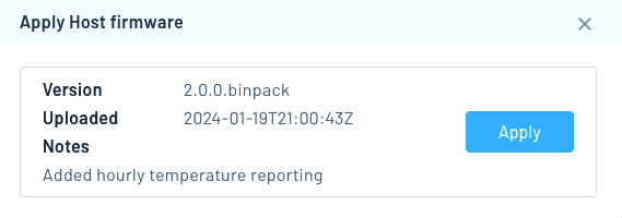
In the resulting dialog, click Apply on the firmware version that you'd like to apply to your device.
You can also apply firmware updates to devices using the Perform DFU Action Notehub API request.
Applying the DFU Action to the Host
Once you've queued up a firmware update in Notehub, the Notecard detects a new host binary is available on its next inbound sync and downloads the firmware into its own flash storage.
The Notecard will then perform a RESET on the host microcontroller, which
places it into its ROM bootloader. Then, using a microcontroller-specific
communications protocol, the Notecard reprograms the various areas in flash as
directed by instructions within the firmware image file, verifies them via MD5
hashes, and restarts the MCU.
On hosts that use the MCUboot bootloader (such as the nRF52840), the Notecard triggers MCUboot serial recovery rather than a ROM bootloader, but the rest of the flow (download, flash, verify, and restart) is the same.
You can monitor the progress of the firmware update on your device's Host Firmware tab in Notehub. When the update completes you'll see a Status of "Completed" as shown below.

You can also monitor the progress of a DFU action with the Get Devices DFU Status Notehub API request.
The firmware update process won't begin until the Notecard next syncs with
Notehub. To expedite this process while prototyping, use the
hub.set API to set
"mode":"continuous" and "sync":true. Maintaining a continuous connection
consumes more power, so in production these settings should only be used on
devices with sufficient power (for example, mains- or USB-powered devices).
{
  "req": "hub.set",
  "mode": "continuous",
  "sync": true
}J *req = NoteNewRequest("hub.set");
JAddStringToObject(req, "mode", "continuous");
JAddBoolToObject(req, "sync", true);
NoteRequest(req);req = {"req": "hub.set"}
req["mode"] = "continuous"
req["sync"] = True
card.Transaction(req)