Blues Notecarrier® Datasheet: Notecarrier Pi v2.0
Notecarrier A Series
Notecarrier F Series
Notecarrier Pi Hat Series
- Notecarrier Pi v1.0
- Notecarrier Pi v2.0
Notecarrier X Series
Functional Description
Notecarriers are available in multiple form factors to support rapid development across a range of use cases. Depending on the variant, a Notecarrier may prioritize direct host integration, compact size, integrated cellular/WiFi and GNSS antennas, or the ability to be soldered directly into a low-volume production design.
Notecarriers are explicitly designed to bridge the gap between early prototyping and a production-ready Notecard-based solution. In a final product, the Notecard is typically socketed directly onto a custom PCB via an edge connector, alongside the customer's MCU, sensors, and supporting circuitry. While this approach provides maximum flexibility and modularity, it can significantly increase the effort required during initial development and validation.
To simplify this process, Notecarriers expose the Notecard's interfaces through convenient breakout connections and integrate essential supporting circuitry, including power regulation, protection, and signal conditioning. This allows developers to focus on firmware, connectivity, and system behavior without first designing a complete custom carrier board.
Features
- Simple. Provides breadboard compatible pins or solderable mask for direct connections.
- Compatible. Level shifters ensure compatibility with 3.3V or 5V equipment.
- Convenient. Powered by a USB connector (requires 2A supply).
- GPS Ready. Models are either active GPS compatible, or feature a built-in antenna to enable GNSS connectivity.
Compatible Notecards
Due to differences in the physical size of Notecards, certain Notecarriers are only compatible with certain Notecards. However, the Notecarrier Pi v2.0 is compatible with all available Notecards:
Differences Between Notecarrier Pi and Other Notecarriers
There are several key differences between the Notecarrier Pi and other Blues Notecarriers. Specifically, the Notecarrier Pi:
- Has no support for battery monitoring or charging.
- Supports 3V3 only and is powered directly by the Raspberry Pi.
- Doesn't offer I2C clock stretching (therefore I2C errors are more common).
- Doesn't support the Notecard's AUX 1-4 pins (therefore card.aux is not supported).
- Provides serial access via AUX RX/TX (therefore there is limited support for card.aux.serial).
Package Configuration
Notecarrier Pi (Raspberry Pi Hat) v2.0
Notecarrier Pi (CARR-PI) is designed for drop-in development with a Raspberry Pi or compatible Single Board Computer. This Notecard must be powered by a Raspberry Pi or compatible SBC.
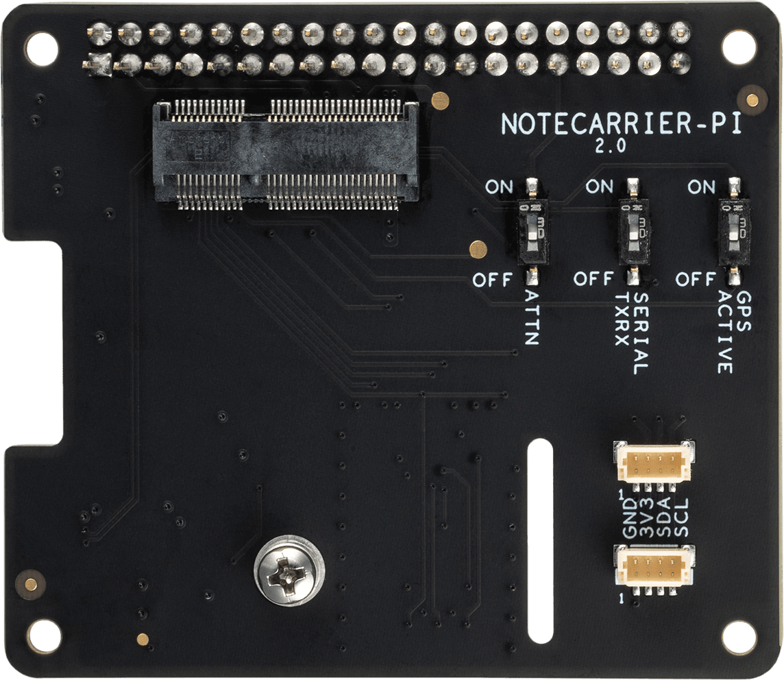
| Front | Back |
|---|---|
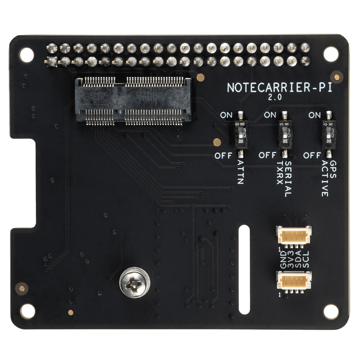 | 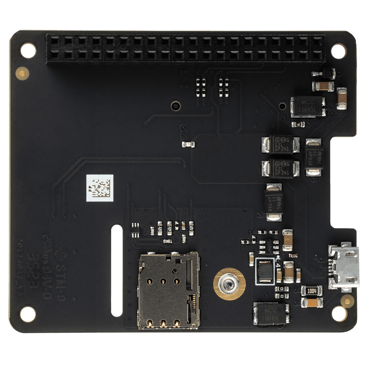 |
- Pre-soldered stackable 40-pin header for plugging directly into a Raspberry Pi and stacking additional Pi hats.
- Notecard edge connector socket and mounting screw receptacle.
- Micro-USB port to power Notecarrier and provide a USB Serial command interface to Notecard.
- External Nano-SIM slot for additional carrier connectivity.
- DIP switches (shown below) to configure diagnostic serial port, attention pin, and active GPS support.
- Requires user provided U.FL cellular/WiFi antenna and optional U.FL active GPS antenna.
- PCB Dimensions: 56mm x 65mm
- Center of Mounting Holes: 52mm x 61mm (measured from the edge of the PCB to the center of the furthest mounting hole)
- 2 Qwiic ports for attaching external peripherals to your project.
Power Information
The Micro-USB port on the Notecarrier Pi is a data-only port and does not provide power to the Notecarrier. Make sure to power your project with a Raspberry Pi, or use an alternate power method, including:
-
attaching a LiPo battery.
The LiPo battery must be a single-cell 3.7V battery with a 2-pin JST PH connector.
-
applying 2.5-5.5VDC to the
V+pin.Commonly provided via DC power supply or non-rechargeable battery.
Typical USB ports may only be capable of supplying 500 mA of current, which might not be enough to power Notecard during a cellular connection to a GSM network (which can spike to 2A). In this situation, you're advised to supplement power to your Notecarrier with an external source (e.g. a LiPo battery).
GPS (GNSS) Antenna Requirements
All Notecarrier models are designed to support active GPS, and several Notecarrier models provide built-in antennas ready to be connected to a Cellular Notecard using the included u.FL cables.
Active GPS Ready
The Notecarrier B, Notecarrier Pi, and Notecarrier R models do not have integrated GPS antennas, but support active GPS by providing circuitry to enable bias voltage to be supplied.
The Notecarrier is built to support either an active or passive GPS antenna, and
has a DIP switch to enable you to select your configuration. The DIP switch
connects the Notecard's VACT_GPS_OUT to VACT_GPS_IN to support active GPS
antennas that accept voltages in the 3.3V-4V range*.
*VACT_GPS_OUT is only powered when the cellular modem is active.
Header Descriptions
Notecarrier Pi 40-Pin Header
Notecarrier Pi is configured as a Pi Hat. As such, the Notecarrier Pi follows the standard 40-pin Raspberry Pi Model B+ layout.
The Raspberry Pi 40-pin GPIO connector used has 0.64mm square pins.
Pi 40-pin Header Pin Usage
| Pin # | Pin Name | Dedicated | Description |
|---|---|---|---|
| 1 | 3V3 | N | 3.3VDC power |
| 2 | 5V | N | 5VDC power |
| 3 | SDA | N | I2C data (Notecard has onboard 10K pull-up resistors) |
| 4 | 5V | N | 5VDC power |
| 5 | SCL | N | I2C clock (Notecard has onboard 10K pull-up resistors) |
| 6 | GND | N | Ground |
| 8 | AUX_RX | Y/N (DIP) | High-speed diagnostic interface |
| 9 | GND | N | Ground |
| 10 | AUX_TX | Y/N (DIP) | High-speed diagnostic interface |
| 14 | GND | N | Ground |
| 20 | GND | N | Ground |
| 25 | GND | N | Ground |
| 30 | GND | N | Ground |
| 31 | ATTN | Y/N (DIP) | Configurable interrupt signal |
| 34 | GND | N | Ground |
| 39 | GND | N | Ground |
DIP Switches
There are three DIP switches are located on the board. The switches are used to reserve exclusive access to the GPIO pins.
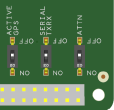
-
ACTIVE GPS- When turnedON, applies 3.9VDC to the center conductor of the Notecard GPS antenna connector to power the low-noise amplifier (LNA) of an active GPS antenna. This switch must beOFFif Notecard is used with a passive GPS antenna! However, we recommend an active antenna for best performance. -
SERIAL TXRX- When turnedON, enables serial communication with Notecard via NotecardAUX_RXandAUX_TXvia Raspberry Pi GPIOs 14 and 15 (Pins 8 and 10). Typical applications will use I2C for Notecard interactions, with this AUX serial port providing useful debugging features for developers. -
ATTN- When turnedON, connects Notecard ATTN to Raspberry Pi GPIO 6 (Pin 31).
Specifications
Electrical Characteristics
DC Characteristics
| Description | Minimum | Maximum | Unit |
|---|---|---|---|
| Supply Voltage | 2.5 | 5.5 | V |
| Supply Current | 500 | 2000 | mA |
Absolute Maximum Ratings
| Description | Minimum | Maximum | Unit |
|---|---|---|---|
| Storage temperature | -35 | 70 | °C |
Actual values may vary based on local conditions such as atmospheric conditions and distance to the cell tower.
Ordering Information
Design Files
Open source hardware designs for all Notecarriers are maintained in the note-hardware GitHub repository.
Here are the design files available for the Notecarrier Pi v2.0:
- Schematic (
.pdf) — the full circuit schematic. Use it to understand how the Notecard, Raspberry Pi interface, power, and I/O are wired together. - PCB drawing (
.pdf) — a printable drawing of the PCB layers, drill details, and board outline for reference and mechanical fit. - PCB layout (
.brd) — the native Cadence Allegro board layout. Open it in Allegro/OrCAD PCB Editor to view or modify the design. - Gerber fabrication files (
.zip) — the Gerber and drill set. Send this package to a PCB manufacturer to have bare boards produced. - 3D model (
.stp) — a STEP 3D model. Import it into mechanical CAD to check fit and design enclosures.
Board Errata
Terms and Conditions
Visit Blues Hardware Terms & Conditions.
Revision History
| Author | Date | Summary |
|---|---|---|
| Ray Ozzie | 2019-2020 | Document drafted |
| John Wiedey | 2020 | Various improvements |
| Sean Taylor | 2020 | Various improvements |
| Zachary J. Fields | 01 OCT 2020 | Updated information and translated to markdown |
| Brandon Satrom | 04 JAN 2021 | Added link to design resources |
| Greg Wolff | 13 JAN 2021 | Added BAT pin information to Notecarrier AF datasheet |
| Brandon Satrom | 07 APR 2022 | Added Notecarrier A information |
| Zachary J. Fields | 20 JUL 2022 | Added Notecarrier F information |
| Zachary J. Fields | 24 OCT 2022 | Added Notecarrier B v2 information |
| Rob Lauer | 28 OCT 2022 | Added versioning for Notecarrier B v1/v2 |
| TJ VanToll | 05 JAN 2023 | Added Notecard Outboard Firmware Update information |
| Rob Lauer | 28 FEB 2023 | Re-labeling Notecarrier B as "Basic" |
| Rob Lauer | 01 MAR 2023 | Added PCB/Mounting Hole Dimensions |
| Rob Lauer | 07 SEP 2023 | Added Notecarrier F v1.3 information |
| Rob Lauer | 16 NOV 2023 | Added Notecarrier Pi v2.0 information |
| Rob Lauer | 14 MAR 2024 | Added Notecarrier B v3.1 and Notecarrier R v1.0 information |
| Rob Lauer | 05 JUN 2024 | Added Notecarrier XS v1.1 information |
| Rob Lauer | 10 JUN 2024 | Added KiCad schematics to A, B, F, and Pi Notecarriers |
| Rob Lauer | 18 JUL 2024 | Added Notecarrier XS v1.2 information |
| Rob Lauer | 22 JUL 2024 | Updated Notecarrier pin descriptions |
| TJ VanToll | 19 AUG 2024 | Added Notecarrier X v1.2, XM 1.2, and XP 3.1 information |
| Rob Lauer | 14 JAN 2026 | Added Notecarrier CX v1.3 information |
| Rob Lauer | 11 FEB 2026 | Added Notecarrier A v2.3 information |
| Rob Lauer | 22 MAY 2026 | Added Notecarrier CX v1.7 information |
| Rob Lauer | 11 JUN 2026 | Added Notecarrier XI v1.4 information |
Contact Information
Blues Inc.
https://blues.com
50 Dunham Ridge Suite 1650
Beverly, MA 01915
support@blues.com