Notecarrier CX Quickstart
Watch a video of this tutorial
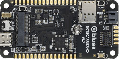
In this tutorial you'll learn how to set up and flash firmware to the Notecarrier CX's onboard STM32L433-based host MCU.
By the end of this guide you'll have flashed a working blink sketch to the Notecarrier CX's host. The guide covers two methods for flashing firmware—over USB and via an STLINK programmer—so you can choose the approach that works best for your setup. It also covers step debugging with the STLINK, so you can set breakpoints and inspect your firmware as it runs.
 note
noteThis guide shows how to flash firmware to the Notecarrier CX using Arduino IDE because of its ease of use. After completing this quickstart tutorial, you may wish to try out one of the following alternative platforms for writing host firmware:
Prerequisites
Before working with firmware in Arduino IDE, you must first complete the following prerequisites.
-
Download and install Arduino IDE.
-
Download and install STM32CubeCLT, which is a toolset that allows third-party environments to work with STM32-based host MCUs.
noteAlternatively, you may install both STM32CubeIDE and STM32CubeProgrammer. These are much larger software packages that may not be necessary for your local development environment. Be sure to also follow these installation notes when installing STM32CubeProgrammer.
-
Set the DIP switch next to the USB-C connector to
HST. After making the change, fully power down the Notecarrier CX, then power it back on.
Linux-only setup required for accessing the device in DFU mode and virtual COM port.
-
Create a
/etc/udev/rules.d/rule for the device in DFU mode.(echo '# DFU (Internal bootloader for STM32 MCUs)'; echo 'SUBSYSTEM=="usb", ATTRS{idVendor}=="0483", ATTRS{idProduct}=="df11", MODE="0664", GROUP="plugdev"') | sudo tee /etc/udev/rules.d/49-stdfu-permissions.rules > /dev/null -
Create a
/etc/udev/rules.d/rule for the device's virtual COM port.(echo '# Virtual COM Port for STM32 MCUs'; echo 'SUBSYSTEM=="usb", ATTRS{idVendor}=="0483", ATTRS{idProduct}=="5740", MODE="0664", GROUP="plugdev"') | sudo tee /etc/udev/rules.d/49-stvcp-permissions.rules > /dev/null -
Add active user to
plugdevgroup in/etc/group.sudo usermod -aG plugdev $USER
Using the Arduino CLI
As an alternative to using Arduino IDE to configure and build your project, you can use the Arduino CLI.
-
In order to specify the board, you need to first install the STM32duino core. You'll need a minimum of version
2.9.0of the STM32duino core installed.arduino-cli core install STMicroelectronics:stm32 -
You can then select the Notecarrier CX's host MCU with the
CYGNETboard part number. For example:arduino-cli compile --fqbn STMicroelectronics:stm32:Blues:pnum=CYGNET blinky.ino
Configuring Arduino IDE
With Arduino IDE installed, you next need to configure your environment to build and flash code to your Notecarrier CX.
Installing STM32duino in the Arduino IDE
-
Within Arduino IDE open your Settings/Preferences.
-
Locate the Additional boards manager URLs (see screenshot below), and add the following URL:
https://github.com/stm32duino/BoardManagerFiles/raw/main/package_stmicroelectronics_index.json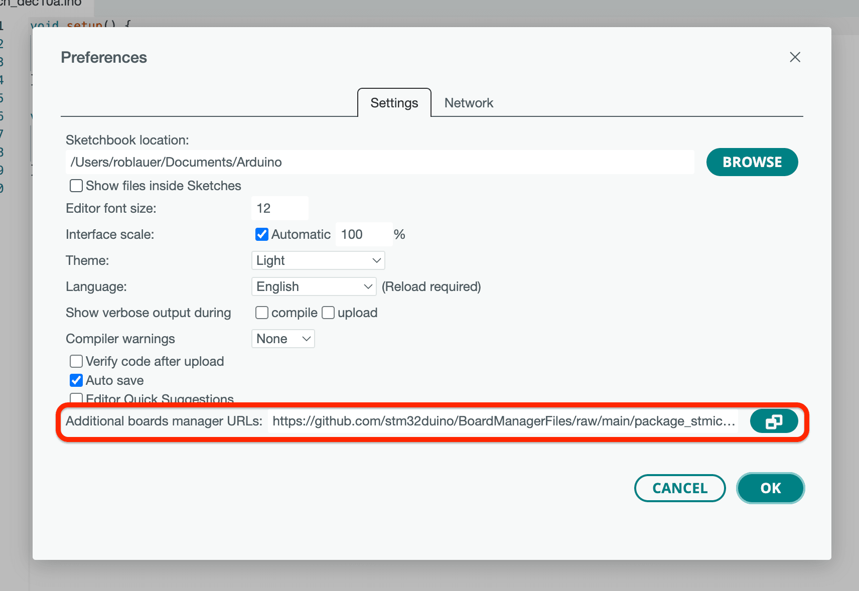
-
Click OK to save your changes, and then restart Arduino IDE.
-
Next, click the Boards Manager icon (second icon down in the left panel), search for STM32 MCU based boards, and install version
2.9.0or greater.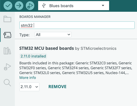
-
Restart Arduino IDE.
 warning
macOS 27 (Golden Gate) and later: Arduino IDE's bundled ctags tool is an
Intel-only binary and needs Rosetta 2, which macOS 27 removes when you upgrade
(and macOS 28 drops entirely). Without it, every build fails with
ctags: bad CPU type in executable, and the IDE never prompts you to install
Rosetta because the failing process isn't an app you launched. In order to
build you’ll need to reinstall Rosetta from your Terminal with the following
command:
softwareupdate --install-rosetta --agree-to-licenseUsing STM32duino in the Arduino IDE
-
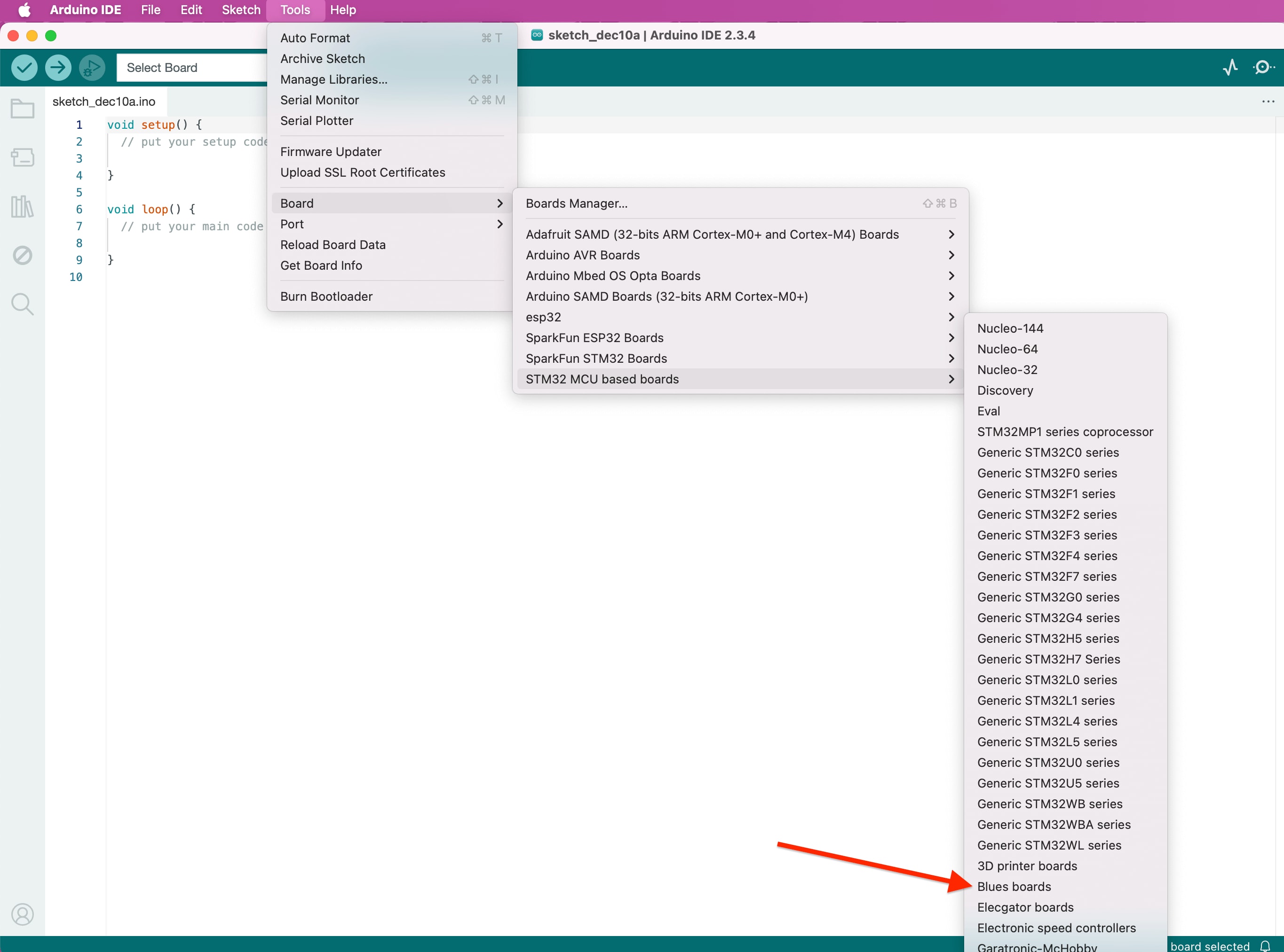
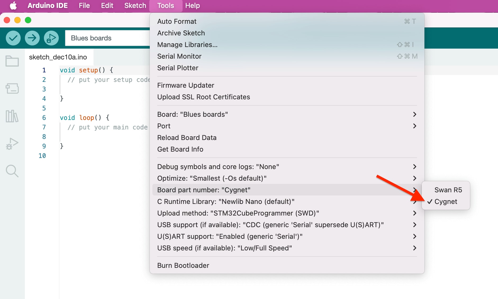
Under Tools > Board, select STM32 MCU based boards, and then Blues boards.
-
Next, under Tools > Board part number, select Cygnet.
-
Lastly, under Tools > USB support (if available), select CDC (generic 'Serial' supersede U(S)ART).
Flashing Firmware
Now that you have Arduino IDE configured to work with the Notecarrier CX, you're ready to flash firmware.
To do so, we recommend using a programmer like the STLINK-V3MINI; however, you may also program the Notecarrier CX via a USB cable connected to your computer.
Programming the Notecarrier CX with the STLINK-V3MINI (Recommended)
-
In Arduino IDE, under Tools > Upload method, select STM32CubeProgrammer (SWD).
-
Plug the STLINK-V3MINI into your computer over USB.
-
Plug the Notecarrier CX into a power source (e.g. a LiPo battery or your computer via USB).
NOTE: If you want to see Serial output from the Notecarrier CX, you need to either use a USB cable as the power source or customize your sketch to use the STLINK-V3MINI for Serial output.
-
Plug the ribbon cable from the STLINK-V3MINI into the Notecarrier CX's debug jack.

-
Skip to the Blink the Onboard LED instructions below.
Programming the Notecarrier CX without the STLINK-V3MINI
-
In Arduino IDE, under Tools > Upload method, select STM32CubeProgrammer (DFU).
-
Connect the Notecarrier CX's USB-C port to your computer with a USB cable.
 warning
The DIP switch next to the USB-C connector must be in the
HSTposition for USB flashing to work. In theNCposition the USB data lines go to Notecard instead of the host MCU, and Arduino IDE will not find a device in DFU mode. See Prerequisites if you haven't set it yet. -
Press and hold the
BOOTbutton on the Notecarrier CX, press and releaseRST(reset), then releaseBOOTto cause the Notecarrier CX to jump into its bootloader. This sequence must be done every time you want to upload firmware to the Notecarrier CX. -
Proceed to the Blink the Onboard LED instructions below.
Blink the Onboard LED
-
In the Arduino IDE, use File > New Sketch to create a new sketch.
-
Overwrite the provided boilerplate code with the following to cause the onboard LED to blink repeatedly:
// the setup function runs once when you press reset or power the board void setup() { // initialize digital pin LED_BUILTIN as an output. pinMode(LED_BUILTIN, OUTPUT); } // the loop function runs over and over again forever void loop() { digitalWrite(LED_BUILTIN, HIGH); // turn the LED on (HIGH is the voltage level) delay(1000); // wait for a second digitalWrite(LED_BUILTIN, LOW); // turn the LED off by making the voltage LOW delay(1000); // wait for a second } -
Use the Upload button to upload this sketch to your Notecarrier CX.
If the Notecarrier CX's LED blinks on and off every second—you're good to go! Follow the next section if you have an STLINK programmer and want to learn about step debugging, or move on to the next steps.
 tip
tipLet AI write your firmware. Blues Expert MCP connects your AI coding assistant (Claude Code, GitHub Copilot, Cursor) directly to our API docs, providing live request validation and firmware best practices for Arduino, C, Zephyr, and Python. Install the Blues Expert MCP →
Step Debugging with Arduino IDE (Optional)
The Notecarrier CX supports step debugging with Arduino Native Debugging on Arduino IDE when used with an attached STLINK programmer/debugger.
Debugging requires SWD, so if you flashed over USB you'll need to attach an STLINK and change Tools > Upload method to STM32CubeProgrammer (SWD) before continuing.
-
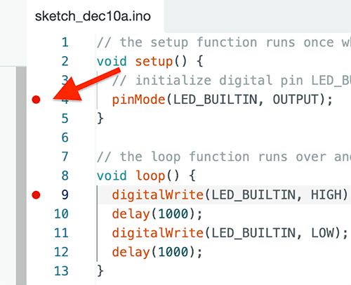
Set one or more breakpoints on your sketch.
-
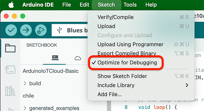
In the Sketch menu, select Optimize for Debugging.
-
Upload the sketch to the Notecarrier CX.
-
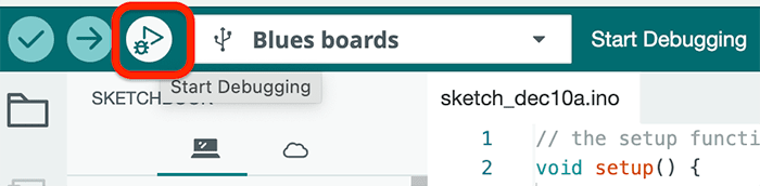
Click the Start Debugging button.
-
When a breakpoint is hit, use the Arduino IDE to step through relevant code blocks and inspect variables, view the call stack, and watch expressions.

Next Steps
Congratulations! You've configured your Notecarrier CX and flashed new firmware to it using Arduino IDE.
If you're following a Cell+WiFi Quickstart, next we recommend building your first IoT app:
Use the Notecard to Send DataSet Up Your Microcontroller- Build Your First IoT App With Blues
- Send Data to Your Cloud
At any time, if you find yourself stuck, please reach out on the community forum.
